WhatsApp: +86 16626708626
 Email:
 Phone: +86 16626708626
Description
Core Product Summary
The Bosch Rexroth VT-VRPA1-50-1X (material number R900952202) is an analog electronic amplifier from the VT-VRPA1-5…-1X component series 1X, built to control proportional hydraulic valves with electrical position feedback. It converts a 0 to +10 V command value into a pulse-modulated solenoid current while closing a PID position control loop around the valve’s inductive position transducer, so valve spool position follows the electronic setpoint with repeatable accuracy.
The card is a 100 x 160 mm Euro-card (approximately 35 mm high, front plate 7 modular spacings) with a DIN 41612-F32 plug connector for installation in 19″ racks or a suitable card holder, and it operates from a nominal 24 VDC supply (battery 21 to 40 V, or rectified single-phase AC 21 to 28 V). Depending on the solenoid version, the controlled output stage delivers up to 2.7 A at 25 W (size 6 valves) or 3.7 A at 50 W (size 10 valves). The card provides an enable input, cable-break detection for the actual-value cable, short-circuit-proof outputs, front-panel trimming potentiometers for zero point and sensitivity, and LED indication of enable, cable break, and supply undervoltage.
Key Technical Specifications
| Parameter | Value |
|---|---|
| Product type | Analog amplifier (plug-in Euro-card) for proportional valves with electrical position feedback |
| Component series | VT-VRPA1-5…-1X, series 1X (component series 10 to 19: unchanged technical data and pin assignment) |
| Control principle | Closed-loop position control with PID behavior; pulse-modulated (clocked) output stage; fast energizing and de-energizing for short actuating times |
| Circuit board format | 100 x 160 x approx. 35 mm (W x L x H), Euro format with front plate, 7 modular spacings |
| Plug connection | DIN 41612 – F32 |
| Supply voltage | Nominal 24 VDC at b16/b2; battery 21…40 V; rectified AC Ueff = 21…28 V (single-phase, full-wave) |
| Smoothing capacitor | Connected separately at b16–b2 (recommended: capacitor module VT 11110); required only if supply ripple > 10% |
| Valve solenoid (max.) | 2.7 A / 25 W (size 6) or 3.7 A / 50 W (size 10), depending on the amplifier version |
| Power consumption | Max. 35 W (2.7 A version) or 60 W (3.7 A version) |
| Current consumption | Max. 1.5 A (2.7 A version) or 2.5 A (3.7 A version) |
| Solenoid output | Rectangular (square-wave) voltage, pulse-modulated, at b6–b8; Imax. 2.7 A or 3.7 A |
| Command value inputs | 0…+10 V differential input (UE III at z10/z12; UE I, UE II, UE III available) |
| Signal source (command value) | Potentiometer Ri = 1 kΩ, supplied with +10 V from b32 (10 mA), or external source |
| Position feedback | Inductive position transducer (oscillator b26; test point z28, 0…+10 V); transducer cable max. 50 m at 100 pF/m |
| Enable input | z16, U = 8.5…40 V (e.g. 10 V from z32); green LED lights up when enabled |
| Adjustments | Trimming potentiometers for zero point and sensitivity |
| Fault indication | Switching output z26: +24 V (max. 100 mA) = no error, 0 V = error; detects actual-value cable break, UB too low, ±15 V stabilization fault |
| LED displays | Green: enable; yellow: cable break (actual value); red: UB < approx. 21 V |
| Short-circuit-proof outputs | Output stage to solenoid; signal to position transducer; potentiometer supply |
| Ambient temperature | 0 to +70 °C |
| Storage temperature | −20 to +70 °C |
| Weight | 0.37 kg |
Detailed Product Overview
The VT-VRPA1-50-1X sits between the machine’s electrical control system and a proportional hydraulic valve. The controller supplies a 0 to +10 V command value on the card’s differential input; the card’s oscillator/demodulator section excites the valve’s inductive position transducer and demodulates its return signal into an actual-value voltage, and the PID position controller drives a pulse-width-modulated output stage so the solenoid current — and therefore the valve opening — tracks the commanded value. Because the loop is closed around actual spool position rather than just current, the card compensates for flow forces, spring nonlinearity, and solenoid resistance changes caused by coil heating.
The output stage is deliberately pulsed rather than linear. Rectangular voltage modulation wastes little power in the amplifier and produces the fast energization and de-energizing times that high-response valves need, while the closed-loop current control holds the commanded solenoid current at up to 2.7 A (size 6 valves) or 3.7 A (size 10 valves). The solenoid must be connected directly to the card: the valve solenoid must not be fitted with freewheeling diodes or other external protective circuits, which would distort the current waveform the control loop measures.
Integration planning centers on the power supply, the wiring, and the rack. The card runs from a nominal 24 VDC supply, and it accepts battery voltages from 21 to 40 V or a rectified single-phase AC supply of 21 to 28 Veff; where the supply ripple exceeds 10%, an external smoothing capacitor — the VT 11110 capacitor module is recommended — must be connected, and power zero (b2) must be bridged to control zero (b12), either directly at the DIN connector when the power supply is within 1 m or by routing the control zero separately to ground at greater distances. Cable cross-sections are specified: 1.5 mm² for solenoid cable up to 20 m and 2.5 mm² for 20 to 60 m, 1.5 mm² for supply and capacitor, and shielded cable is recommended for signal and solenoid lines, with the shield connected to the control cabinet as extensively and short as possible. The card may only be plugged and unplugged when de-energized.
Diagnostics are built in. The card continuously monitors the actual-value cable for breaks, the supply for undervoltage below approximately 21 V, and the internal ±15 V stabilization; a fault switches the z26 output to 0 V for evaluation by the PLC, and front-panel LEDs show enable (green), cable break (yellow), and undervoltage (red). Commissioning is done through two trimming potentiometers on the front plate — zero point and sensitivity — which align the card’s characteristic with the specific valve. Within the VT-VRPA1-5…-1X family, versions with the 527 serial number drive 2.7 A solenoids and versions with 537 drive 3.7 A solenoids, and the valve adaptations are matched to Rexroth proportional valves such as DBETFX, DREB6X, DBEB10Z/DREB10Z/DBETBX, 4WRP6EA/3FREZ, and 4WRP10EA, so the card variant must be confirmed against the exact valve before replacement or reuse in a new design.
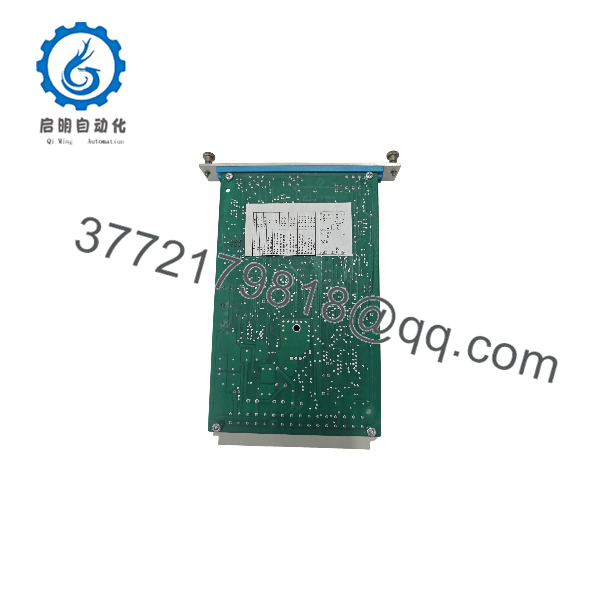
VT-VRPA1-50-1X R900952202
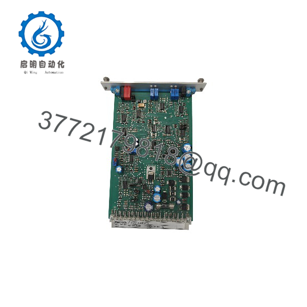
VT-VRPA1-50-1X R900952202
System Compatibility & Integration Requirements
| Item / Dependency | Verified Compatibility or Requirement | Practical Note |
|---|---|---|
| Valve type | Proportional valves with electrical position feedback (inductive position transducer) | Family versions adapted to valve types DBETFX, DREB6X, DBEB10Z/DREB10Z/DBETBX, 4WRP6EA/3FREZ, and 4WRP10EA; confirm the exact card variant against the valve before ordering |
| Solenoid versions | Serial 527 = 2.7 A solenoid (size 6, 25 W); serial 537 = 3.7 A solenoid (size 10, 50 W) | The material number R900952202 covers the VT-VRPA1-50-1X type; the solenoid variant must match the installed valve |
| Mounting | Euro-card in 19″ rack, or open card holder VT 3002-1-2X/32F (see data sheet 29928) | Card holder installation is permitted only inside a control cabinet |
| Connector | DIN 41612 – F32 | All supply, setpoint, feedback, and solenoid connections are routed through this plug |
| Supply | 24 VDC nominal; battery 21…40 V or rectified AC 21…28 Veff | Add smoothing (VT 11110 capacitor module) if ripple exceeds 10%; bridge power zero b2 to control zero b12 |
| Enable signal | 8.5…40 V at z16 (e.g. 10 V from the card’s own z32 reference) | Output stage is disabled until enabled |
| Cable limits | Solenoid cable: 1.5 mm² up to 20 m, 2.5 mm² for 20 to 60 m; position transducer: max. 50 m at 100 pF/m; supply and capacitor 1.5 mm² | Shielded cable recommended for signal and solenoid lines |
| External protection | No freewheeling diodes or other protective circuits on the valve solenoid | External clamping distorts the pulsed current control |
| Test and service equipment | Test box VT-PE-TB1, test adapter VT-PA-3 | For checking and service in the VT-VRPA1 family |
Dimensions, Mounting & Connection Notes
| Item | Value |
|---|---|
| Board format | 100 x 160 x approx. 35 mm (W x L x H), Euro-card format |
| Front plate | 7 modular spacings (TE) |
| Plug connector | DIN 41612 – F32 (32-pin) |
| Weight | 0.37 kg |
| Mounting | Plug-in card for 19″ racks or open card holder VT 3002-1-2X/32F (control cabinet only) |
| Ambient temperature | 0 to +70 °C |
| Storage temperature | −20 to +70 °C |
| Front plate elements | Trimming potentiometers for zero point and sensitivity; LEDs: green (enable), yellow (cable break), red (UB undervoltage) |
Installation notes: plug or unplug the card only when de-energized. Keep more than 1 m of distance to aerial lines, radios, and radar systems, and do not route solenoid and signal lines near power cables. Bridge power zero (b2) and control zero (b12); at less than 1 m from the power supply unit, make the bridge directly on the DIN connector, and at greater distances, lead the control zero separately to ground. Comply with the specified cable lengths and cross-sections, connect cable shields to the control cabinet extensively and as short as possible, and connect the card only to a solenoid without freewheeling diodes or other protective circuits.
FAQ
What is the Bosch Rexroth VT-VRPA1-50-1X?
It is an analog Euro-card amplifier (material number R900952202) from the VT-VRPA1-5…-1X component series 1X that controls proportional hydraulic valves with electrical position feedback, using a PID position control loop and a pulse-modulated output stage.
What power supply does the card need?
It runs on a nominal 24 VDC supply, accepting battery voltages from 21 to 40 V or rectified single-phase AC from 21 to 28 Veff; an external smoothing capacitor (the VT 11110 module is recommended) is required if the supply ripple exceeds 10%.
How much solenoid current can it deliver?
The controlled output stage delivers up to 2.7 A at 25 W for size 6 valves or up to 3.7 A at 50 W for size 10 valves, depending on the amplifier version; maximum power consumption is 35 W or 60 W and maximum current consumption is 1.5 A or 2.5 A respectively.
What command signal does it accept?
A 0 to +10 V command value on the differential input, taken from an external voltage source or from a 1 kΩ potentiometer powered by the card’s own +10 V reference (10 mA available at b32).
How is the card mounted and connected?
It is a 100 x 160 mm Euro-card with a DIN 41612-F32 connector, installed in a 19″ rack or in the VT 3002-1-2X/32F open card holder inside a control cabinet; it may only be plugged or unplugged when de-energized.
How is the card matched to the valve?
Two front-panel trimming potentiometers adjust zero point and sensitivity, aligning the card’s characteristic to the specific valve; within the family, 527 serial versions suit 2.7 A solenoids and 537 versions suit 3.7 A solenoids, with variants adapted to valves such as DBETFX, DREB6X, DBEB10Z, DREB10Z, DBETBX, 4WRP6EA, 3FREZ, and 4WRP10EA.
What fault monitoring is built in?
The card detects actual-value cable breaks, supply undervoltage below approximately 21 V, and ±15 V stabilization faults, signaling an error by switching output z26 to 0 V (otherwise +24 V, max. 100 mA) and via green, yellow, and red LEDs on the front plate; the outputs to the solenoid, position transducer, and potentiometer supply are short-circuit-proof.
What cable lengths and cross-sections are permitted?
Solenoid cable up to 20 m at 1.5 mm² and 20 to 60 m at 2.5 mm²; position transducer cable up to 50 m at 100 pF/m; supply and capacitor wiring at 1.5 mm². Shielded cable is recommended for signal and solenoid lines, and no freewheeling diodes or protective circuits may be fitted to the valve solenoid.