WhatsApp: +86 16626708626
 Email:
 Phone: +86 16626708626
Description
Key Technical Specifications
| Parameter | Specification |
|---|---|
| Manufacturer | B&R Industrial Automation |
| Order Number | 3NC154.60-2 |
| Module Designation | NC154 |
| Product Family | System 2005 |
| Product Type | Three-axis positioning module |
| Number of Axes | 3 |
| Incremental Encoder Input | 5 V differential |
| Maximum Encoder Input Frequency | 150 kHz per axis |
| Counter Resolution | 32-bit |
| SSI Absolute Encoder | Supported |
| Maximum SSI Word Length | 31 bits |
| SSI Baud Rate | Up to 230 kbaud |
| Analog Output | ±10 V, 12-bit resolution per axis |
| Encoder Power Supply | 5 V DC or 24 V DC |
| Digital Inputs | Four 24 V DC sink inputs plus one trigger input per axis |
| Relay Output | 24 V AC / 24 V DC, 1 A per axis |
| Internal Working Memory | 2 MB DRAM |
| System Memory | 2 MB FlashPROM |
| Maximum Power Consumption | 6 W |
| Operating Temperature | 0°C to +55°C |
| Mounting Format | Double-width System 2005 module |
| Status Indication | LED indicators |
| Certifications | CE; cULus listing documented by B&R |
| Required Terminal Blocks | 3 × TB162; order separately |
| Positioning Software | 1A3502.01, NC154.60-2 standard operating system |
Sources: B&R’s official product page and System 2005 technical documentation.
Compatibility note: The NC154.60-2 belongs to the legacy B&R System 2005 platform. Confirm rack compatibility, CPU support, software availability, and the existing axis configuration before ordering a replacement. The module’s terminal blocks are not included in the standard module order data.
Product Introduction
The B&R 3NC154.60-2 is a three-axis positioning module for the System 2005 PLC platform. Each axis supports incremental encoder feedback up to 150 kHz or SSI absolute encoder feedback, together with a ±10 V, 12-bit analog output for servo control. The module also provides 24 V DC digital inputs and a relay output for axis-related control functions.
This controller is intended for existing machine architectures that require coordinated positioning without replacing the original PLC platform. Before installing a replacement, engineers should verify the encoder type, signal levels, axis parameters, terminal-block configuration, and application software. B&R lists the corresponding TB162 terminal blocks and NC154 positioning software as separate order items.
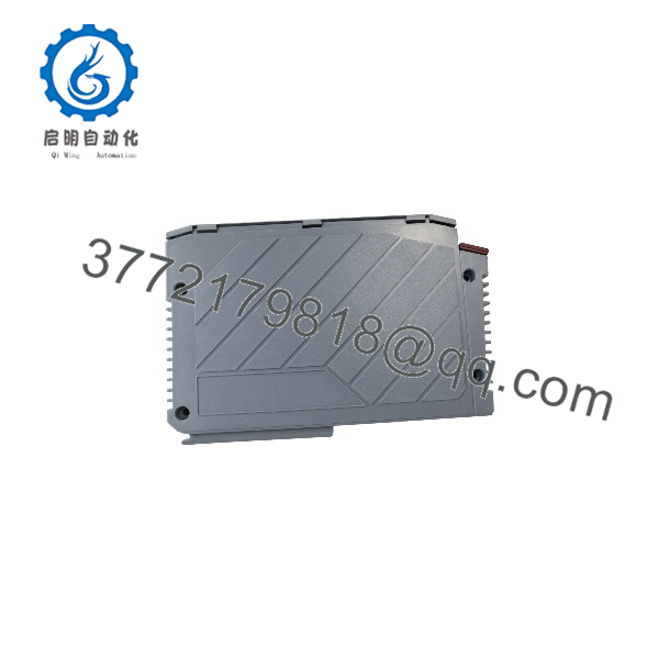
3NC154.60-2
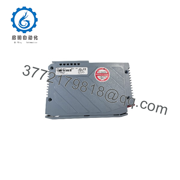
3NC154.60-2
Installation & Configuration Guide
The NC154.60-2 is a legacy motion-control module. Installation should follow the original System 2005 hardware and software documentation. The procedure below is a preliminary replacement workflow, not a substitute for the OEM manual.
Stage 1: Pre-Installation Preparation
Estimated hands-on time: 15–30 minutes, excluding machine shutdown and backup time.
- Secure the machine. Notify operations and place the motion system in an approved safe state.
- Isolate electrical power. Follow the machine’s lockout/tagout procedure and verify that hazardous energy has been removed.
- Record the complete order number, module revision, rack position, CPU type, and existing system configuration.
- Back up the PLC application and positioning parameters using the installed engineering tools.
- Photograph the module’s terminal blocks, encoder wiring, trigger inputs, analog outputs, and relay connections.
- Identify whether each axis uses an incremental encoder or an SSI absolute encoder.
- Confirm the availability of three compatible TB162 terminal blocks and the required NC154 positioning software.
Tools and documentation: ESD protection, suitable insulated tools, a properly rated multimeter, wire labels, a camera, the System 2005 hardware manual, and the existing PLC project files.
⚠️ Do not assume that the original positioning parameters will transfer automatically to a replacement module. Preserve the existing application and document all axis-specific settings before removal.
Stage 2: Removing the Existing Module
Estimated hands-on time: 10–20 minutes.
- Confirm that the machine and control cabinet are in the required safe state.
- Verify electrical isolation before touching terminals or removing the module.
- Label all field wiring and document each terminal-block position.
- Disconnect the terminal blocks using the manufacturer’s recommended procedure.
- Release the module’s retaining mechanism and remove it from the rack without damaging the backplane connector.
- Inspect the rack slot, connector contacts, and surrounding modules for contamination or mechanical damage.
- Retain the original module until the replacement has passed functional acceptance testing.
⚠️ Do not remove or insert the module under power unless the exact hardware documentation explicitly permits the operation.
Stage 3: Installing the Replacement
Estimated hands-on time: 15–30 minutes.
- Verify that the replacement is marked 3NC154.60-2 and matches the required hardware configuration.
- Confirm that the rack and CPU support the NC154 module.
- Install the module in the designated System 2005 slot and secure it according to the hardware manual.
- Install the three required TB162 terminal blocks if they are not already available.
- Reconnect the encoder, trigger-input, analog-output, and relay wiring using the verified terminal assignments.
- Confirm the encoder supply voltage before connecting each encoder. The module documentation identifies 5 V DC and 24 V DC encoder-supply options.
- Check signal polarity, differential encoder wiring, shielding, grounding, and analog-output connections.
- Verify that the original positioning software and axis configuration are available.
Pre-commissioning checklist
Stage 4: Power-On and Functional Testing
Estimated hands-on time: 30–60 minutes, depending on application complexity.
- Inspect the module installation and field wiring before restoring power.
- Restore power according to the System 2005 startup procedure.
- Check the module’s LED indicators and compare their states with the OEM documentation.
- Confirm that the PLC recognizes the positioning module.
- Verify encoder feedback for each axis before enabling motion.
- Check the analog servo command using the approved commissioning procedure and appropriate test equipment.
- Verify trigger inputs, digital inputs, and relay outputs without bypassing machine safety functions.
- Test axis direction, position feedback, travel limits, and motion response under controlled conditions.
- Validate synchronization or electronic gearing if the application uses those functions.
- Record diagnostic messages, positioning parameters, and acceptance-test results.
⚠️ Do not enable motion until encoder polarity, feedback scaling, axis direction, and travel limits have been verified. Incorrect feedback configuration can cause uncontrolled movement or a collision.
Frequently Asked Questions (FAQ)
Q1: What is the B&R 3NC154.60-2 used for?
It is a three-axis positioning module for the B&R System 2005 PLC platform. It processes incremental or SSI absolute encoder feedback and provides analog servo commands for positioning applications.
Q2: What is the maximum encoder input frequency?
The specified incremental encoder input frequency is 150 kHz per axis. The module uses a 32-bit counter and also supports SSI absolute encoders. Check the encoder’s electrical interface and signal characteristics before connecting it.
Q3: Are the TB162 terminal blocks included?
The official order data states that three terminal blocks must be ordered separately. The listed accessory is 3TB162.9, a 12-pin screw-clamp terminal block. Confirm the terminal blocks included in the supplier’s quotation before purchasing.
Q4: Can the 3NC154.60-2 be replaced with a newer B&R positioning module?
Not automatically. A newer module may use a different hardware platform, configuration method, communication architecture, or software environment. Check the existing System 2005 rack, CPU, PLC program, encoder interfaces, analog servo connections, and motion-control requirements before selecting a successor.
Q5: Is the NC154.60-2 suitable for SSI absolute encoders?
Yes. The official B&R documentation specifies SSI absolute encoder support in addition to incremental encoder inputs. It lists an SSI word length of up to 31 bits and a baud rate of up to 230 kbaud in the technical documentation. Verify the encoder’s SSI format and timing requirements before commissioning.
Q6: Is the B&R 3NC154.60-2 obsolete?
It is a legacy System 2005 product. The current lifecycle status and remaining OEM support should be confirmed directly with B&R. For procurement, request the unit’s actual condition, serial-number photographs, available test documentation, warranty terms, and dispatch lead time.
Q7: What software is required to configure the module?
B&R lists 1A3502.01, the NC154.60-2 standard positioning operating system, as a related software item. Confirm the required software package, programming cable, CPU compatibility, and existing project format before attempting to load or modify the configuration.