
 WhatsApp: +86 16626708626
 Email:
  Phone: +86 16626708626
Description
Key Technical Specifications
| Parameter | Value |
|---|---|
| Manufacturer | B&R Industrial Automation |
| Product family | Automation Panel 500 |
| Model designation | 5AC600.GPI0-K05 |
| Product type | Industrial HMI operator panel |
| Display technology | TFT industrial display platform |
| Touch function | Configuration dependent |
| Panel communication | B&R Panel interface |
| System compatibility | B&R Automation PC / Panel systems |
| Mounting method | Cabinet panel mounting |
| Application software | B&R Visualization / Automation Runtime environment |
| Protection rating | Front protection depends on panel configuration |
| Operating environment | Industrial machine automation |
| Replacement category | Legacy spare part |
Note: B&R ordering codes encode hardware options through multiple characters. The complete identification label, including display size, touch option, and revision, should be checked before ordering.
Product Introduction
The B&R 5AC600.GPI0-K05 is an Automation Panel 500 series operator interface component designed for industrial machine visualization and control applications. It belongs to the B&R HMI hardware family used with Automation PC systems and Automation Runtime-based machine architectures.
This type of panel is commonly maintained in installed production equipment where replacing the complete operator interface is preferred over redesigning the visualization system. Compatibility depends on the installed B&R Automation Studio project, visualization version, panel configuration, and communication hardware.
Installation & Configuration Guide
Stage 1 — Pre-Installation Preparation (~10 minutes)
- Notify production personnel about the planned HMI replacement.
- Apply lockout/tagout procedures before opening the control cabinet.
- Verify the 24 VDC supply is isolated.
- Allow stored energy discharge before handling electronics.
Tools Required:
- ESD wrist strap
- PH1 screwdriver
- Multimeter
- Wire labels
- Smartphone/camera for documentation
Data Backup:
- Save the existing B&R Automation Studio project.
- Back up visualization files.
- Record:
- Panel model number
- Hardware revision
- IP settings
- Communication parameters
- Photograph all rear connectors and cable routing.
⚠️ Do not assume a physically matching panel contains the same visualization configuration.
Stage 2 — Removing the Existing Panel (~10 minutes)
- Switch the machine to a safe maintenance state.
- Disconnect 24 VDC power.
- Label all communication cables.
- Disconnect panel communication and power connectors.
- Release panel mounting clamps.
- Remove the operator panel carefully.
- Inspect connectors and cabinet cutout.
⚠️ Keep the original panel until the replacement has completed commissioning.
Stage 3 — Installing the Replacement Panel (~10 minutes)
- Wear ESD protection.
- Confirm the replacement marking:
5AC600.GPI0-K05
- Compare:
- Display size
- Connector arrangement
- Touch configuration
- Mechanical dimensions
- Install the panel into the cabinet opening.
- Secure mounting clamps evenly.
- Reconnect power and communication cables.
- Verify cable shielding and grounding practices.
Self-Checklist:
- Correct B&R part number verified
- Mechanical fit confirmed
- Communication cable installed
- Grounding checked
- Power polarity verified
Stage 4 — Power-On & Testing (~15 minutes)
- Verify 24 VDC polarity with a multimeter.
- Energize the panel.
- Confirm startup sequence.
- Verify communication with the Automation PC/controller.
- Load or verify the visualization application.
- Test:
- Touch input
- Operator buttons
- Alarm pages
- Trend displays
- Machine status screens
- Perform a controlled machine dry run.
- Record final configuration.
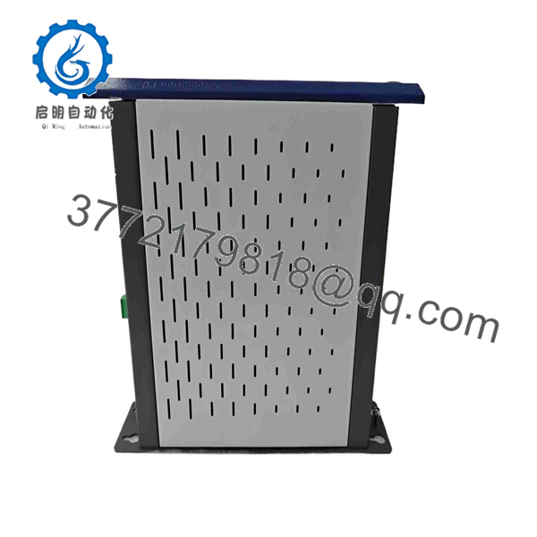
5AC600.GPI0-K05
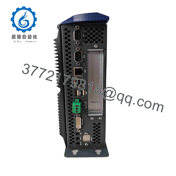
5AC600.GPI0-K05
Technical Pitfall & Survival Guide
❗ The most common replacement error is ordering only from the short model number.
B&R Panel 500 ordering codes contain hardware configuration information. Two panels may look identical but differ in display size, touch technology, communication interface, or firmware compatibility.
❗ Visualization software compatibility matters.
A replacement panel may power on correctly but fail to display the machine interface if the Automation Studio visualization project does not match the installed hardware configuration.
❗ Always document the old panel before removal.
I have seen machine downtime extended because technicians removed the original panel before saving the IP address, connector layout, and visualization backup. Five minutes with a camera before removal can prevent hours of troubleshooting.
Frequently Asked Questions (FAQ)
What is the B&R 5AC600.GPI0-K05?
The 5AC600.GPI0-K05 is a B&R Automation Panel 500 series industrial HMI component used for machine operator visualization and control.
Is this a PLC CPU module?
No. This is an operator interface/HMI component. The control logic normally runs in a separate B&R controller or Automation PC running Automation Runtime.
Is the 5AC600.GPI0-K05 obsolete?
It should be treated as a legacy spare component. B&R Panel 500 products are maintained mainly for existing machine installations. Confirm lifecycle status with B&R for the exact hardware revision.
Can I replace it directly with another B&R Panel?
Not always. Verify display size, touch option, communication interface, Automation Studio visualization compatibility, and hardware revision before installation.
Will the machine program be stored inside this panel?
Usually not. The PLC logic and machine application normally reside in the controller or Automation PC. However, visualization files and panel-specific settings must still be verified.
Why are surplus B&R panels cheaper than OEM replacements?
Legacy automation parts are often available through surplus inventory or tested refurbished channels. The price difference usually reflects lifecycle availability rather than a difference in application purpose.
What should I verify before purchasing?
Confirm:
- Complete part number: 5AC
- Hardware revision
- Display condition
- Touch operation
- Connector condition
- Power-on test results
- Compatibility with the installed B&R Automation Studio project
For used or surplus units, request identification-label photos and functional test records before installation.



