
 WhatsApp: +86 16626708626
 Email:
  Phone: +86 16626708626
Description
Key Technical Specifications
| Parameter | Value |
|---|---|
| Manufacturer | B&R Industrial Automation |
| Material Number | 5PC600.SX02-01 |
| Product Family | Automation PC 620 |
| Product Designation | APC620 system unit |
| Product Type | Fanless industrial PC / control system unit |
| Supply Voltage | 24 V DC ±25% |
| Nominal Current | 3.8 A |
| Typical Inrush Current | 7 A |
| Maximum Inrush Current | 40 A for less than 300 µs |
| Expansion Slots | 2 × PCI |
| Drive Bays | 1 × drive slot |
| CompactFlash Slot 1 | 1 × CompactFlash slot |
| Serial Interfaces | 2 × RS-232 |
| USB Interfaces | 2 × USB 2.0 Type A |
| USB Transfer Rates | 1.5 Mbit/s, 12 Mbit/s, and 480 Mbit/s |
| USB Port Current | 500 mA maximum per connection |
| Ethernet Interfaces | 2 × shielded RJ45 |
| Ethernet Speed | 10/100 Mbit/s |
| Display Interface | Smart Display Link / DVI-I |
| Audio | AC97 sound interface |
| Keyboard / Mouse Interface | PS/2 |
| Battery | Renata, 950 mAh |
| Battery Service Life | Approximately 4 years |
| Enclosure Protection | IP20 per EN 60529 |
| Required Power Terminal Block | 0TB103.9 screw-clamp or 0TB103.91 cage-clamp, ordered separately |
| Product Status | Discontinued by manufacturer; confirm actual inventory before purchase |
B&R specifies the 5PC600.SX02-01 as an APC620 system unit with two PCI slots, one drive slot, two RS-232 interfaces, two USB 2.0 ports, Smart Display Link/DVI-I, two 10/100 Ethernet ports, AC97 sound, PS/2 keyboard/mouse support, and 24 V DC power. The required power terminal block is separate and must be ordered as 0TB103.9 or 0TB103.91.
Product Introduction
The B&R 5PC600.SX02-01 is an Automation PC 620, or APC620, industrial computer system unit for machine control, HMI hosting, data handling, and industrial communications. It runs on 24 V DC and provides two PCI expansion slots, a CompactFlash slot, one drive slot, dual 10/100 Ethernet, two RS-232 ports, two USB 2.0 ports, and Smart Display Link/DVI-I display connectivity.
This B&R APC620 is commonly retained in legacy equipment because it preserves established machine hardware, Automation Studio projects, PCI add-on cards, display architecture, and cabinet wiring. The exact SX02-01 configuration matters: a different APC620 variant may have different expansion, storage, processor, or interface provisions. Document the existing CompactFlash media, PCI cards, battery status, terminal block type, BIOS settings, and installed operating system before replacing the unit.
Troubleshooting Quick Reference
| Symptom | Possible Cause | Relevance to This Part | Quick Check Method | Recommendation |
|---|---|---|---|---|
| APC620 does not power up | Missing 24 V DC supply, blown fuse, reversed polarity, failed power input circuitry | ✅ High | Measure 24 V DC directly at the input terminal block while attempting startup; verify polarity and check upstream fuses | Prove stable power first; replace the PC only after correct voltage reaches the unit |
| PC starts briefly, then resets | Supply sag, excessive inrush, weak 24 V DC PSU, poor terminal connection, battery or hardware issue | ✅ High | Monitor voltage during startup; check whether the supply dips during the specified inrush event; inspect terminal torque | Use a properly sized 24 V DC supply and correct loose terminals before condemning the |
| No image on connected display | Incorrect display source, loose Smart Display Link/DVI-I connection, failed display panel, failed graphics hardware | ✅ Medium | Test with a known-good compatible display and cable; inspect connector retention with power removed | Diagnose the display and cable path first; replace the system unit only if the output remains absent with verified accessories |
| Unit powers up but does not boot the machine application | Missing or failed CompactFlash media, corrupted operating system, BIOS configuration change, damaged drive | ✅ High | Check boot LEDs or BIOS messages; image the CompactFlash media if accessible; test with an approved backup image | Preserve original media before any replacement; a good cannot restore a missing or corrupt application by itself |
| System date and BIOS settings keep resetting | Exhausted internal battery | ✅ Medium | Record BIOS settings, shut down normally, remove power, wait, then check retained date and settings | Replace the specified battery through an approved service procedure; the listed battery life is about four years |
| Ethernet link LEDs remain off | Bad patch cable, switch-port fault, damaged RJ45 port, network configuration issue | ✅ Medium | Test with a known-good cable and switch port; verify link LEDs and check IP settings from the operating system | Check the plant network first; replace the only after port-level testing confirms a hardware fault |
| Network link works but machine communication fails | IP address conflict, wrong subnet, firewall rule, PLC program issue, driver or protocol configuration | ❌ Low to Medium | Compare IP settings, gateway, subnet mask, and service configuration against the backed-up system documentation | Do not replace the industrial PC before checking software, network configuration, and PLC communication diagnostics |
| USB keyboard or flash drive is not detected | Bad device, damaged USB port, operating-system driver issue, insufficient port power | ✅ Medium | Test each USB port with a known-good low-power keyboard; inspect port contacts; review device-manager logs | Check drivers and the USB device first; if all known-good devices fail, inspect the hardware |
| PCI card is not detected after replacement | Card not seated, slot incompatibility, BIOS settings, missing driver, card failure | ✅ Medium | Power down, use ESD protection, reseat the card, photograph slot positions, and check BIOS/device manager | Move PCI cards one at a time and preserve the original slot order; do not assume all PCI cards are interchangeable |
| Random freezes or corrupt files | Aging CompactFlash media, overheating, unstable power, failing RAM, operating-system corruption | ✅ High | Review event logs, monitor cabinet temperature, check 24 V DC ripple and load behavior, then create a storage image | Back up the application and storage first; investigate power and media health before replacing the system unit |
| No response from serial device | Incorrect baud rate, wrong RS-232 cable type, port assignment change, failed external device | ❌ Low to Medium | Confirm baud rate, parity, stop bits, and cable pinout; test with a known-good serial device or loopback plug | Do not replace the until serial settings and field wiring are verified |
| PC failed after handling or service | Electrostatic discharge, connector damage, bent pins, incorrect PCI insertion | ✅ Medium | Inspect connectors under magnification and review whether ESD controls were used during service | Use a grounded wrist strap and inspect for mechanical damage before installing a replacement |
❗ Power-input warning: The nominal input is 24 V DC ±25%, with a typical 7 A startup inrush and a short maximum inrush of 40 A for less than 300 µs. A weak or poorly selected 24 V DC supply can make a healthy industrial PC look defective. Measure voltage during startup, not only when the machine is idle.
❗ Storage warning: Before pulling the original unit, make a verified image of its CompactFlash card or installed boot media where site policy permits. I have seen a replacement PC installed correctly, only for the line to remain down because the original CompactFlash image was corrupted during a rushed transfer. Preserve the old media, label it, and do not write to it until you have a confirmed backup.
If you are stuck, provide technical support with the complete 5PC600.SX02-01 label, revision number, photos of installed PCI cards, CompactFlash media, 24 V DC terminal block, boot screen, status LEDs, BIOS messages, and operating-system logs.
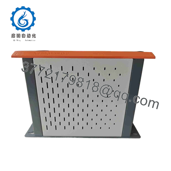
5PC600.SX02-01
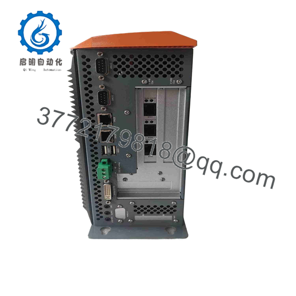
5PC600.SX02-01
Frequently Asked Questions (FAQ)
What is the B&R 5PC600.SX02-01?
The B&R 5PC600. is an Automation PC 620 industrial computer system unit. It supplies the computing platform for B&R machine-control and visualization applications, with 24 V DC power, dual Ethernet, serial and USB interfaces, CompactFlash storage support, display connectivity, and two PCI expansion slots.
Is the 5PC600. a PLC CPU or an industrial PC?
It is an industrial PC system unit, not a conventional rack-mounted PLC CPU. Depending on the machine architecture, it may host B&R automation software, HMI software, data services, communication drivers, and PCI-based interfaces. The actual control application, operating system, fieldbus hardware, and display arrangement depend on the installed project and optional hardware.
Can I replace 5PC600. with any system unit?
No. Match the complete material number first. variants can differ in processor configuration, storage arrangement, installed interfaces, PCI availability, hardware revision, and operating-system support. A replacement can look physically similar and still fail to support the machine’s CompactFlash image, PCI cards, Automation Studio version, or connected display arrangement.
Can I hot-swap the B&R ?
No. Shut down the application, isolate the 24 V DC supply, and follow your site lockout/tagout procedure before removal. The is not intended for energized replacement. Removing power while the system is writing to CompactFlash or another drive can corrupt the boot media and add a software-recovery problem to a hardware replacement.
Will I lose my machine program when replacing the ?
Potentially. The application may be stored on CompactFlash, a drive in the internal drive slot, or another storage device in the system. Make a verified backup or image before moving anything. Also record the operating-system version, Automation Studio version, BIOS settings, network addresses, PCI-card locations, serial-device settings, and any license files. Treat the original storage media as the machine’s recovery master until the replacement has been proven in operation.
What terminal block do I need for the 24 V DC power input?
B&R lists the 0TB103.9 screw-clamp terminal block and 0TB103.91 cage-clamp terminal block as separate ordering items for this system unit. Check whether the existing terminal block is present, undamaged, and compatible before ordering. Do not assume it is included with a surplus .
Why does the restart when motors or contactors energize?
The usual cause is a 24 V DC power-quality problem rather than a failed PC. Motor starts, contactor coils, brake releases, and solenoid banks can create voltage dips, electrical noise, or ground disturbances. Measure the input voltage at the terminal block while the event occurs, inspect protective-earth bonding, check supply sizing, and confirm that the power supply can accommodate startup inrush. The unit’s listed input is 24 V DC ±25%, but a transient dip can still reset the computer before a handheld meter catches it.
Why might a New Surplus cost less than a factory replacement?
New Surplus inventory may come from an unused project spare, canceled machine build, distributor inventory reduction, or legacy plant stock. It can cost less because the is discontinued and does not move through the current OEM sales channel. Ask for actual-unit photos, serial-number images, seal and packaging photos, proof of 24 V DC startup testing, BIOS access confirmation, port tests, and written warranty terms.
What should I transfer from the old to the replacement?
Transfer only after documenting every item and making a backup. Typical items include CompactFlash or other boot media, PCI expansion cards, approved memory modules, drive hardware, software licenses, network configuration, and display connections. Photograph PCI slot positions and cable routing first. It is the most common rookie mistake to move a PCI card into a different slot, boot the system, and then lose a hardware driver association or communication mapping. Take a picture before you touch anything.



