
 WhatsApp: +86 16626708626
 Email:
  Phone: +86 16626708626
Description
Key Technical Specifications
| Parameter | Specification |
| Manufacturer | B&R (Bernecker + Rainer) |
| Model Number | 7CP476.60-1 |
| Product Family | System 2005 |
| Module Type | Central Processor Unit (CPU) |
| Processor Architecture | B&R System 2005 Processor Platform |
| Operating System Support | Automation Runtime (AR010 or higher) |
| Application Memory | Integrated SRAM / Flash Memory Options |
| Serial Interfaces | 1x RS232 Interface |
| Backplane Bus | System 2005 Parallel Backplane Bus |
| Status Indicators | LEDs for Power, Run, Error, and Battery Status |
| Supply Voltage | Powered via System 2005 Backplane / Power Supply Module |
| Operating Temperature | 0°C to +55°C |
Product Introduction & Supply Chain Strategy
The B&R 7CP476.60-1 is a central processing unit designed for the legacy System 2005 control platform. It manages complex machine logic execution, high-speed task scheduling, and serial communication interfacing across automated manufacturing lines, plastics machinery, and packaging systems.
Because B&R has transitioned the System 2005 series to legacy status, an unexpected CPU failure can lead to extended factory shutdowns. Sourcing refurbished CPU cards introduces severe risks, including degraded onboard SRAM chips, weakened solder joints, and dying lithium backup batteries. Securing a genuine New Surplus 7CP476.60-1 CPU provides a zero-runtime, factory-clean drop-in replacement that eliminates costly redesigns and protects your facility against long-term operational downtime.
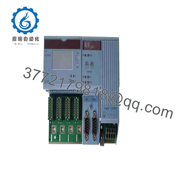
7CP476.60-1
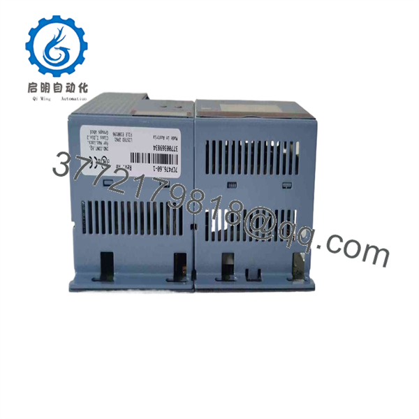
7CP476.60-1
Installation & Configuration Guide
1.Stage 1: Pre-Installation (Prep & Safety):Power Isolation & Program Backup.
- Perform complete Electrical Lock-Out/Tag-Out (LOTO) on the System 2005 rack power supply module.
- Ensure a complete project backup (.br or Automation Studio project file) is stored on a service PC before removing the old CPU.
- Wear a grounded ESD wrist strap before touching the card edge or backplane pins.
- Photograph all jumper settings, memory card orientations, and serial cable routing.
2.Stage 2: Removal:Card Extraction.
- Disconnect the RS232 communication cable from the front port.
- Loosen the top and bottom card retaining screws securing the CPU module to the System 2005 rack chassis.
- Pull the module straight out using the ejector clips to prevent bending backplane connector pins.
3.Stage 3: Installation (Clone & Seat):Jumper Verification & Seating.
- Check all onboard DIP switches and jumpers on the new 7CP476.60-1 module to ensure they mirror the original unit.
- Transfer the PCMCIA/Flash memory card (if equipped) from the old CPU to the replacement board.
- Slide the replacement CPU smoothly into the designated rack slot and tighten the mounting screws securely.
- Reconnect the RS232 serial cable and ensure the connector locking screws are tight.
4.Stage 4: Power-On & Testing:Logic Transfer & Verification.
- Apply 24 VDC power to the rack supply module and monitor the boot LED sequence.
- Verify that the RUN LED illuminates green and no red DIAG or FAIL LEDs remain lit.
- If memory was not stored on an external Flash card, connect via Automation Studio to download the runtime application and system hardware configuration.
- Execute a low-speed dry run of connected field outputs to confirm proper logic execution.
Firmware/Software Versions & Upgrade Notes
- Automation Studio Compatibility: Programming and hardware configuration require B&R Automation Studio (Version 2.x or 3.x, depending on target system setup).
- Automation Runtime Versioning: Confirm that the target CPU firmware/Automation Runtime (AR010 or higher) matches the compiled project dependencies. Uploading a project compiled for a different runtime version can cause a system boot halt (BOOT FAIL).
- RAM Battery Retention: Always verify that a fresh backup battery is installed in the 7CP476.60-1 CPU module prior to commissioning to prevent memory loss during main power dropouts.
Frequently Asked Questions (FAQ)
Q: Why is a New Surplus 7CP476.60-1 CPU preferable to a refurbished board?
A: Refurbished processor cards often carry thousands of operating hours under high cabinet temperatures, leading to thermal stress micro-fractures and degraded electrolytic capacitors. Our New Surplus inventory consists of unused, zero-runtime hardware that offers OEM-grade reliability and avoids premature field failure.
Q: Is this unit guaranteed to be genuine B&R manufacture?
A: Yes. All stock is guaranteed authentic original B&R equipment. Every CPU module undergoes visual inspection, pin integrity checks, and power-on verification before shipment.
Q: Is the B&R System 2005 line obsolete?
A: Yes, the System 2005 product family has been discontinued by B&R. Sourcing new surplus replacement modules like the 7CP476.60-1 allows plant engineers to keep existing machinery running reliably without requiring a costly retrofit to newer X20 hardware platforms.
Q: Can I replace this CPU module while the rack is powered?
A: No. System 2005 CPU modules are not hot-swappable. Removing or inserting a CPU card while the backplane bus is energized will cause electrical transients that can damage the CPU or adjacent I/O modules.
Q: Will the CPU retain its application program when disconnected from power?
A: Application logic stored on non-volatile Flash/memory cards is retained indefinitely. However, dynamic data blocks stored in volatile SRAM rely on the internal backup battery. Replace the battery if the board has been in storage for an extended period.
Q: What warranty coverage comes with this New Surplus unit?
A: We provide a full 1-Year Comprehensive Replacement Warranty. If any operational defect occurs under normal operating conditions within 12 months, we will replace the unit or issue a full refund.



