
 WhatsApp: +86 16626708626
 Email:
  Phone: +86 16626708626
Description
Key Technical Specifications
| Parameter | Value |
|---|---|
| Manufacturer | B&R Industrial Automation |
| Model | 7DI138.70 |
| Module Designation | DI138 |
| System | B&R System 2003 |
| Product Type | Digital input module |
| Digital Inputs | 10 |
| Rated Input Voltage | 24 VDC |
| Input Circuit | Sink |
| Event Counter Inputs | 2 |
| Maximum Input Frequency | 20 kHz |
| Input Filter — Inputs 5 & 6 | ≤3 µs |
| Input Filter — Other Inputs | ≤1.3 ms |
| Connection | Screw-in module |
| Required Terminal Block | 7TB712.9 or 7TB712.91 |
| Terminal Block Type | 12-pin screw clamp / cage clamp |
| Terminal Wire Capacity | 1.5 mm² |
| Certifications | CE, UKCA |
| HazLoc | cULus E180196, Class I Division 2, Groups ABCD |
The B&R product page specifies the 10 inputs, 24 VDC sink configuration, two event-counter channels, 20 kHz input frequency, and separately ordered TB712 terminal block. The B&R System 2003 catalog further specifies the fast hardware filtering on inputs 5 and 6 and the slower filtering on the remaining inputs.
Important: Some reseller pages contain conflicting specifications—for example, one current listing states a 40 kHz counter frequency. B&R’s official product page and System 2003 documentation specify 20 kHz, so 20 kHz should be used for engineering decisions unless the installed hardware revision documentation confirms otherwise.
Product Introduction
The B&R 7DI138.70 (DI138) is a System 2003 digital input module providing 10 × 24 VDC sink inputs. Two inputs have special event-counter capability, with B&R documentation specifying a maximum input frequency of 20 kHz. The module is implemented as a screw-in module and requires a compatible 7TB712 terminal block.
This module is particularly relevant to legacy B&R System 2003 and compatible Power Panel installations. When replacing one, verify the exact module revision and terminal-block configuration. B&R lists 7TB712.9 screw-clamp and 7TB712.91 cage-clamp terminal blocks as required accessories.
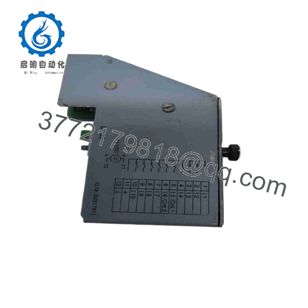
7DI138.70
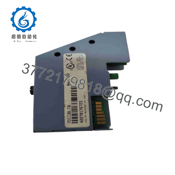
7DI138.70
Installation & Configuration Guide
Stage 1: Pre-Installation Preparation — Approximately 10 minutes
⚠️ Safety First: Put the machine into its approved safe state, isolate the 24 VDC control supply, and apply the site’s LOTO procedure before removing the module.
Tools Required:
- ESD wrist strap
- Multimeter
- Small screwdriver
- Wire labels
- Smartphone/camera
- PLC programming/service equipment
Data Backup:
- Record the complete part number: 7DI138.70.
- Record the hardware revision.
- Photograph the front and terminal arrangement.
- Document all 10 input assignments.
- Identify which channels are used for high-speed/event counting.
- Record the connected terminal block type.
- Save the PLC/application configuration.
- Record any input filtering or counter parameters configured in the application.
⚠️ Do not assume every input has the same response time. B&R documentation specifies particularly fast hardware filtering for inputs 5 and 6.
Stage 2: Removing the Old Module — Approximately 5 minutes
- Stop the machine using the approved shutdown procedure.
- Isolate the 24 VDC supply.
- Verify the field voltage is absent.
- Label all connected input wires.
- Photograph the terminal arrangement.
- Disconnect the field wiring.
- Remove the terminal block.
- Release the screw-in module.
- Withdraw the 7DI138.70 carefully.
- Inspect the mounting/interface area for contamination or mechanical damage.
⚠️ Keep the original module until commissioning is complete. Its terminal labeling and revision information can be useful if a channel behaves differently after replacement.
Stage 3: Installing the New Module — Approximately 5–10 minutes
- Verify the exact model: 7DI138.70.
- Check that the replacement is the correct DI138 variant.
- Verify the terminal block is compatible.
- Install the module into the System 2003/compatible interface.
- Secure the module.
- Reinstall the 7TB712 terminal block.
- Reconnect each input according to the original documentation.
- Check the 24 VDC polarity and field common.
- Verify the two event-counter channels are wired to the correct inputs.
- Inspect all terminals before powering the system.
Configuration Clone — Crucial:
Check:
- Input channel assignment
- Sink wiring
- Input polarity
- Event-counter assignment
- Counter reset behavior
- Counter direction, if applicable
- Input filtering
- PLC I/O mapping
The 7DI138.70 is also documented for use with B&R CP interface applications, where the screw-in module type can be read and automatic operating mode can be controlled by the CPU interface.
Stage 4: Power-On & Testing — Approximately 10 minutes
- Energize the 24 VDC control supply.
- Confirm the B&R controller recognizes the module.
- Activate each digital input individually.
- Verify the corresponding input status.
- Test inputs 5 and 6 at the required pulse frequency if used as event counters.
- Confirm counter values in the PLC/application.
- Verify that no unexpected I/O diagnostic occurs.
- Test the machine’s interlocks and permissives.
- Perform a controlled machine cycle.
- Return the system to automatic operation after all inputs are verified.
Recommended Test Matrix:
| Test | Expected Result |
|---|---|
| 24 VDC field supply | Correct voltage at module input |
| DI 1–4 | Correct ON/OFF state |
| DI 5–6 | Correct digital state and counter operation |
| DI 7–10 | Correct ON/OFF state |
| Counter frequency | Within 20 kHz documented limit |
| PLC I/O mapping | Correct channel correspondence |
| Terminal connection | No loose/intermittent signal |
| Controller diagnostics | No unexpected module fault |
Frequently Asked Questions (FAQ)
What is B&R 7DI138.70?
It is a B&R System 2003 DI138 digital input module with 10 × 24 VDC sink inputs. Two inputs can also be used for event-counter operation.
How many inputs does the 7DI138.70 have?
It has 10 digital inputs, all rated for 24 VDC operation. The input circuit is specified as sink.
What is the maximum input frequency?
B&R’s official product information specifies 20 kHz. Inputs 5 and 6 have a particularly short hardware filter of ≤3 µs, while the other inputs have a hardware filter of ≤1.3 ms.
Which inputs support event counting?
Two inputs support event-counter operation. The System 2003 documentation identifies the module as having two counter-capable inputs.
What terminal block does 7DI138.70 require?
B&R specifies one 7TB712 terminal block, ordered separately. The available options are 7TB712.9 with screw-clamp terminals and 7TB712.91 with cage-clamp terminals. Both are 12-pin terminal blocks for 1.5 mm² conductors.
Is 7DI138.70 obsolete?
The official B&R product page still provides the product information and historical datasheet, but secondary industrial-parts suppliers classify the model as discontinued/legacy. For procurement, treat it as a legacy System 2003 component and verify the physical stock condition and hardware revision before ordering.
Can I substitute 7DI140.70 for 7DI138.70?
Do not assume direct interchangeability. Both belong to the System 2003 screw-in-module family, but B&R documentation distinguishes them by input performance: 7DI138.70 is specified at 20 kHz, while the System 2003 documentation lists 7DI140.70 at 50 kHz. If the existing application uses event counting or timing-sensitive inputs, verify the PLC configuration and module compatibility before substitution.



