
 WhatsApp: +86 16626708626
 Email:
  Phone: +86 16626708626
Description
Key Technical Specifications
| Parameter | Value |
|---|---|
| Manufacturer | B&R Industrial Automation |
| Order Number | 7EX484.50-1 |
| Product ID | EX484 |
| System | B&R System 2003 |
| Product Type | POWERLINK bus controller |
| POWERLINK Interfaces | 4 × RJ45 |
| Ethernet Standard | 100BASE-T / IEEE 802.3 |
| Maximum Data Rate | 100 Mbit/s |
| Maximum Segment Length | 100 m between stations |
| Supply Voltage | 24 VDC |
| Permitted Supply Range | 18–30 VDC |
| Power Consumption | Approximately 20 W |
| I/O Module Power Available | Approximately 10.4 W |
| I/O Bus Interface | 9-pin D-sub socket |
| Station Address | Front-panel station-number dial |
| Electrical Isolation | PLC/control side ↔ POWERLINK interface |
| Protection Rating | IP20 |
| Operating Temperature — Horizontal | 0 °C to +60 °C |
| Operating Temperature — Vertical | 0 °C to +50 °C |
| Storage Temperature | −20 °C to +70 °C |
| Humidity | 5–95%, non-condensing |
| Terminal Block | 0TB704.9 / 0TB704.91 |
| Mounting | System 2003 single-width module |
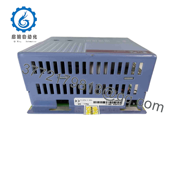
7EX484.50-1
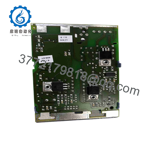
7EX484.50-1
The B&R System 2003 documentation specifies the four-port internal hub, 100BASE-T interface, 100 Mbit/s maximum rate, 18–30 VDC supply range, approximately 20 W power input, IP20 protection, and the station-number dial.
B&R specifies 0TB704.9 as the 4-pin screw-clamp terminal block and 0TB704.91 as the 4-pin cage-clamp version; the terminal block must be ordered separately.
Product Introduction
The B&R 7EX484.50-1 (EX484) is a System 2003 Ethernet POWERLINK bus controller. It provides four RJ45 POWERLINK interfaces through an integrated hub and connects the System 2003 I/O bus to the real-time Ethernet network. The module operates from 24 VDC and provides electrical isolation between the controller and POWERLINK interface.
This is a legacy B&R networking component, so replacement work should focus on maintaining the existing POWERLINK topology and System 2003 I/O configuration. B&R continues to provide the original product page and a version 1.0 datasheet dated June 8, 2004.
Installation & Configuration Guide
Stage 1: Pre-Installation Preparation — Approximately 10 minutes
⚠️ Safety First: Place the machine in its approved safe state. Isolate the 24 VDC control supply and apply the site’s lockout/tagout procedure before removing the EX484 module.
Tools Required:
- ESD wrist strap
- Digital multimeter
- Small screwdriver
- Wire labels
- Camera/smartphone
- POWERLINK diagnostic equipment, if available
Data Backup:
- Record the complete part number: 7EX484.50-1.
- Record the module revision.
- Photograph the module and all four RJ45 connections.
- Record the POWERLINK station number.
- Document the System 2003 I/O modules connected downstream.
- Photograph the 9-pin D-sub I/O bus connection.
- Record the 24 VDC supply wiring.
- Back up the Automation Studio project.
⚠️ The station number is important. The EX484 uses a station-number dial for setting its POWERLINK station address.
Stage 2: Removing the Old Module — Approximately 5 minutes
- Stop the machine using the approved procedure.
- Isolate the 24 VDC supply.
- Verify that the module is de-energized.
- Label the four POWERLINK cables.
- Photograph their port positions.
- Disconnect the RJ45 cables.
- Disconnect the System 2003 I/O bus connection.
- Disconnect the 24 VDC supply.
- Remove the module from its mounting position.
- Inspect the connectors and backplane interface.
⚠️ Do not assume the four RJ45 ports are interchangeable from a network-topology perspective. Preserve the existing cable arrangement during replacement unless the B&R engineering configuration explicitly permits a topology change.
Stage 3: Installing the New Module — Approximately 5–10 minutes
- Verify the exact model: 7EX484.50-1.
- Confirm the replacement is an EX484.
- Install the module in the System 2003 controller position.
- Secure the module mechanically.
- Connect the 9-pin D-sub I/O bus.
- Connect the 24 VDC supply.
- Set the station-number dial to the original value.
- Reconnect each POWERLINK cable to its documented port.
- Verify cable shielding and grounding.
- Check the installation before energizing.
Configuration Clone — Crucial:
Verify:
- POWERLINK station number
- Network topology
- Node configuration
- System 2003 I/O module sequence
- I/O addresses
- Automation Studio hardware configuration
- Error-handling behavior
- 24 VDC supply capacity
The EX484 documentation identifies the module as occupying System 2003 module slot 1 and provides a 9-pin D-sub I/O bus interface.
Stage 4: Power-On & Testing — Approximately 10–15 minutes
- Energize the 24 VDC supply.
- Check the module status LED.
- Confirm the POWERLINK network initializes.
- Verify the station number.
- Check communication with the controller.
- Confirm all downstream System 2003 I/O modules are detected.
- Check I/O diagnostics.
- Verify representative digital and analog channels.
- Check for POWERLINK communication errors.
- Run a controlled machine cycle.
Recommended Test Matrix:
| Test | Expected Result |
|---|---|
| 24 VDC supply | Within 18–30 VDC operating range |
| Module status | Normal |
| Station number | Matches original configuration |
| POWERLINK communication | Network initializes correctly |
| I/O bus | Downstream modules detected |
| Digital I/O | Correct state changes |
| Analog I/O | Correct values |
| Network diagnostics | No unexplained errors |
| Machine cycle | Normal control response |
Frequently Asked Questions (FAQ)
What is B&R 7EX484.50-1?
It is a B&R System 2003 POWERLINK bus controller. It connects System 2003 I/O to an Ethernet POWERLINK network and provides four RJ45 POWERLINK interfaces.
How many POWERLINK ports does the 7EX484.50-1 have?
It has four POWERLINK interfaces through an integrated hub. The documented interface is 100BASE-T with a maximum data rate of 100 Mbit/s.
What power supply does it require?
The module uses 24 VDC, with the documented permissible supply range of 18–30 VDC. The published technical documentation gives approximately 20 W power input.
Does the 7EX484.50-1 include the terminal block?
No. B&R specifies the TB704 terminal block as a separately ordered accessory. The documented options are 0TB704.9 screw clamp and 0TB704.91 cage clamp.
What is the difference between 7EX484.50-1 and 7EX484501?
They refer to the same B&R part, with 7EX484501 commonly used as an alternative condensed reference without punctuation. B&R’s official material number is 7EX484.50-1.
Is 7EX484.50-1 obsolete?
It is a legacy System 2003 component. B&R’s current product site still hosts the product information and original documentation, while specialist suppliers classify available units as legacy/used/new-old-stock inventory.
Can I replace it directly with an X20 POWERLINK module?
Not as a simple plug-in substitution. The X20 platform and System 2003 architecture use different hardware, I/O interfaces, addressing, and engineering configurations. A migration would require checking the controller, POWERLINK topology, I/O modules, Automation Studio project, and machine wiring.
What should I verify before purchasing a replacement?
For a production replacement, verify 7EX484.50-1, module revision, physical condition, station-number configuration, four-port POWERLINK arrangement, System 2003 I/O compatibility, and whether the required TB704 terminal block is already installed at the site. B&R’s original datasheet is dated 2004, so matching the existing hardware configuration is particularly important.



