
 WhatsApp: +86 16626708626
 Email:
  Phone: +86 16626708626
Description
Key Technical Specifications
| Parameter | Value |
|---|---|
| Manufacturer | B&R Industrial Automation |
| Part Number | 80VD100PD.C022-01 |
| Series | ACOPOSmicro 100D |
| Product Type | Dual-axis inverter module / servo drive |
| Controlled Axes | 2 servo motors |
| Motor Feedback | 2 resolver interfaces |
| Fieldbus Interface | X2X POWERLINK |
| Module Supply | 24–64 VDC |
| Nominal Control Voltage | 24 VDC |
| Continuous Output Current | 8 A; confirm derating from the original ACOPOSmicro manual |
| Trigger Inputs | 2 |
| Safety/Enable Input | Enable input provided |
| Motor Brake Interface | Motor holding-brake connection provided |
| Status Indicators | POWERLINK, operating state, module status, and motor-information indicators |
| B&R ID Code | 0xAB6D |
| Mandatory Terminal Block Set | 80XVD100PD.C0-01B |
| Published Weight | Approximately 0.715 kg / 1.58 lb |
| Published Dimensions | Approximately 160 × 65 × 110 mm |
| Lifecycle Status | Legacy / verify current availability before ordering |
B&R identifies the 80VD100PD.C022-01 as an ACOPOSmicro inverter module for two servo motors, with two resolver interfaces, two trigger inputs, a holding-brake connection, an enable input, and X2X POWERLINK status indication. The product page lists 24–64 VDC module supply, 24 VDC nominal voltage, B&R ID code 0xAB6D, and required terminal-block set 80XVD100PD.C0-01B. Secondary distributor references list 8 A continuous current.
Product Introduction
The B&R 80VD100PD.C022-01 is an ACOPOSmicro 100D dual-axis inverter module for controlling two resolver-feedback servo motors from a 24–64 VDC supply. It communicates through X2X POWERLINK and supports two trigger inputs, motor holding-brake connections, and an enable circuit for compact machine motion systems.
This module is designed for an existing B&R motion architecture, not as a universal servo drive. It must match the servo motor winding, resolver feedback, DC supply capacity, POWERLINK topology, brake wiring, terminal-block set, and Automation Studio project. Verify the exact C022-01 suffix and B&R ID code before purchasing.
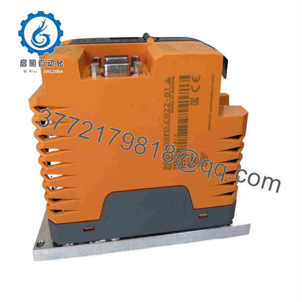
80VD100PD.C022-01
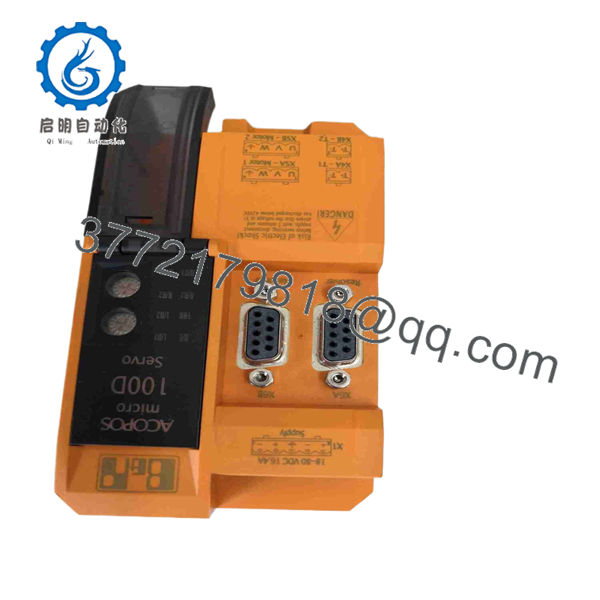
80VD100PD.C022-01
Troubleshooting Quick Reference
| Symptom | Possible Cause | Relevance to This Part | Quick Check Method | Recommendation |
|---|---|---|---|---|
| No LEDs or no module startup | Missing 24 VDC control supply, missing DC motor supply, reversed polarity, blown fuse, failed module | ⚠️ Medium | Measure the 24 VDC control supply and the DC module supply directly at the specified terminal-block pins; verify polarity against the wiring diagram | Confirm both power circuits and fuses before replacing the drive |
| POWERLINK status indicates no communication | Broken network cable, incorrect X2X POWERLINK topology, controller offline, wrong node configuration, network termination issue | ❌ Low | Inspect POWERLINK link/activity LEDs, check controller status, and substitute a known-good network cable if permitted | Diagnose the network first. A communication error does not prove an inverter-module fault |
| One servo axis will not enable | Enable input inactive, safety circuit open, brake not releasing, motor feedback fault, axis-specific output fault | ✅ High | Check enable-input state, brake voltage at the relevant motor terminal, and resolver connector seating for the affected axis | Verify enable, brake, and resolver wiring before replacing the module |
| Both axes will not enable | Missing control supply, global enable circuit open, POWERLINK configuration issue, module internal fault | ⚠️ Medium | Confirm 24 VDC control power, global enable input, controller mode, and diagnostic status | Check common signals before assuming both channels failed simultaneously |
| Axis faults on resolver feedback | Damaged resolver cable, wrong feedback wiring, connector contamination, incompatible motor, failed resolver interface | ✅ High | Power down, inspect resolver connector pins, cable shielding, and connector keying; compare motor part number with the Automation Studio configuration | Swap a known-good resolver cable where possible. Do not substitute encoder wiring for resolver wiring |
| Motor brake does not release | Missing brake supply, wrong brake voltage, open brake coil, brake wiring fault, drive output not enabled | ⚠️ Medium | Measure brake voltage at the motor connector during an enable command and compare it with the motor nameplate | Confirm brake circuit and external supply before replacing the servo module |
| Axis faults on overcurrent during acceleration | Mechanical jam, shorted motor cable, motor winding fault, acceleration too high, wrong motor parameters | ⚠️ Medium | Reduce acceleration for a supervised test; with power isolated, inspect cable and use an OEM-approved motor insulation test method | Diagnose motor, mechanics, and cabling before replacing the drive |
| DC supply collapses when motion starts | Undersized supply, discharged or failed supply capacitor, wiring resistance, external load fault, excessive acceleration | ❌ Low | Measure DC supply voltage at the module while the axis starts; compare supply current with the system design | Correct power supply capacity, wiring, or acceleration profile before replacing the module |
| Axis moves in the wrong direction after replacement | Motor-phase or resolver wiring mismatch, axis configuration mismatch, incorrect project loaded | ✅ High | Run a guarded, low-speed jog and compare commanded direction to actual direction; verify motor and feedback wiring | Stop immediately if the axis moves unexpectedly. Restore the validated Automation Studio configuration |
| Replacement drive will not fit or terminals do not match | Missing required terminal-block set, suffix mismatch, wrong ACOPOSmicro variant | ✅ High | Compare the module label, terminal positions, terminal-block part number, connector keying, and dimensions with the removed drive | Do not force connectors. Confirm the mandatory 80XVD100PD.C0-01B terminal-block set is included or available |
| Module overheats or faults after extended operation | High ambient temperature, blocked airflow, excessive current, poor panel layout, incorrect derating | ✅ High | Measure cabinet ambient temperature and trend actual axis current; inspect ventilation around the module | Correct load, cooling, and panel layout. Verify current derating before replacement |
❗ The resolver connection is not interchangeable with a standard incremental encoder connection. Take photos of both motor-feedback connectors, their shield terminations, and the exact motor part numbers before removing the old 80VD100PD.C022-01. A resolver wiring mistake can cause immediate feedback faults, uncontrolled direction, or an axis that will not enable.
Also check the terminal blocks. B&R identifies 80XVD100PD.C0-01B as mandatory for this module. A correct drive without the correct terminal-block set can delay commissioning or invite incorrect field wiring.
If diagnostics remain unclear, provide technical support with the Automation Studio project version, POWERLINK diagnostics, module LED state, motor nameplate, resolver-cable photos, DC supply measurements, brake voltage, fault history, and full module-label photographs.
Frequently Asked Questions
What is the B&R 80VD100PD.C022-01?
The B&R 80VD100PD. is an ACOPOSmicro 100D dual-axis inverter module. It controls two servo motors, uses two resolver-feedback interfaces, communicates through X2X POWERLINK, supports two trigger inputs, and includes connections for motor holding brakes and an enable input.
What supply voltage does the 80VD100PD. require?
B&R specifies a 24–64 VDC module supply and lists 24 VDC as the nominal voltage. Confirm the actual supply wiring, polarity, fuse size, and power budget from the machine schematic before energizing the replacement. This is a low-voltage DC servo-drive platform, not a 230 V AC or 480 V AC servo amplifier.
Can this drive control two motors independently?
Yes. B&R describes this unit as a control module for two servo motors, with two resolver interfaces. However, each motor must be supported by the configured drive project, correctly wired, and compatible with the module’s current and voltage limits. Verify the original axis parameters and motor data before connecting two axes.
Does the 80VD100PD. support encoders?
The specified feedback interface is for two resolvers. Do not assume an incremental encoder, absolute encoder, or other feedback type will connect directly. Verify the installed motor’s resolver interface, connector pinout, excitation requirements, and the Automation Studio configuration before ordering.
Is the 80XVD100PD.C0-01B terminal-block set required?
Yes. B&R lists 80XVD100PD.C0-01B as the mandatory terminal-block set for ACOPOSmicro modules in the 80VD100PD.xxxx-01 family. Confirm whether the terminal blocks are included with the replacement drive. Do not reuse damaged, melted, loose, or incorrectly keyed connectors.
Can I hot-swap this servo module?
No. Shut down the machine safely, isolate the DC supply, apply lockout/tagout, allow stored energy to discharge, and verify absence of voltage before removing power, motor, resolver, brake, trigger, or network connections. Do not use extinguished LEDs as proof that the DC bus is safe.
Why does one motor fault while the other axis works?
The shared module can be healthy. An individual-axis fault often comes from a resolver cable, motor winding, holding brake, mechanical jam, motor parameter mismatch, or channel-specific wiring. Swap only equivalent cables or test with a known-good motor under controlled conditions. Do not move resolver connections between axes without recording configuration and wiring.
Is the 80VD100PD. obsolete, and should I keep a spare?
Treat this as legacy motion-control hardware and confirm current supply before ordering. For a production-critical machine, keep a tested spare drive, the correct 80XVD100PD.C0-01B terminal-block set, the Automation Studio project backup, motor and resolver records, and a complete photo record of wiring and settings.
What supplier testing should I request?
For New Original / New Surplus stock, request exact label and B&R ID-code verification, photographs of all connectors and terminals, inspection for corrosion or rework marks, confirmation that the module is supplied with or can accept the correct terminal-block set, and ESD-safe packaging.
For Refurbished stock, request testing in a compatible B&R ACOPOSmicro POWERLINK setup with two resolver-feedback servo motors where available. The report should document power-up, POWERLINK communication, module status LEDs, enable-input operation, resolver recognition, controlled motor rotation, direction verification, output-current behavior, trigger-input operation, holding-brake output operation, fault protection, thermal stability, and final QC sign-off. Request actual test photos, video, warranty terms, and the complete part-number photograph before shipment.



