
 WhatsApp: +86 16626708626
 Email:
  Phone: +86 16626708626
Description
Key Technical Specifications
| Parameter | Value |
|---|---|
| Manufacturer | B&R Industrial Automation |
| Part Number | ECCP70-01 |
| CPU Type | MULTI CPU Type B / CP70 |
| Application Memory | 42 KB SRAM |
| Maximum Program Size | Up to 42K instructions |
| Registers | 7,168 |
| Flags | 800 |
| Online Interface | TTY, 62.5 kBaud |
| Application Interface | RS232 / RS485 / TTY |
| RS485 | Electrically isolated, network-capable |
| RS232 | Not electrically isolated |
| TTY Receiver | Electrically isolated |
| Hardware Timers | 512 |
| Software Timers | 64 |
| Timing Pulses | 10 ms, 100 ms, 1 s, 10 s |
| Real-Time Clock | Included |
| Application Memory Module | Not included; PROM/EPROM/EEPROM/Flash-PROM module ordered separately |
| Rack Compatibility | B&R MULTI and MIDI module racks |
| Power Consumption | +8 V: 8.9 W; +15 V: 0.9 W; −30 V: 0.8 W |
| Certification | CE |
The B&R product page confirms the CPU type, 42 KB SRAM, serial interfaces, electrical isolation characteristics, and MULTI/MIDI rack compatibility. The historical CP70 documentation additionally specifies the register count, timers, 62.5 kBaud TTY interface, real-time clock, and power consumption.
Compatibility note: ECCP70-01 belongs to B&R’s legacy CP70/MULTI architecture. It is not an Automation Studio-era X20 or modern ACOPOS controller. Verify the existing rack, application-memory module, firmware/software environment, and interface configuration before ordering a replacement. Historical documentation states that the application program memory module is separate from the CPU.
Product Introduction
The B&R ECCP70-01 is a Type B MULTI CPU for B&R MULTI and MIDI rack-based PLC systems. It provides 42 KB SRAM for application instructions, 7,168 registers, 800 flags, a real-time clock, and serial interfaces including isolated RS485 and TTY.
This CPU is primarily relevant when maintaining an existing legacy CP70 installation. The separate application-memory architecture matters during replacement: the ECCP70-01 itself does not include the PROM/EPROM/EEPROM/Flash-PROM application-memory module.
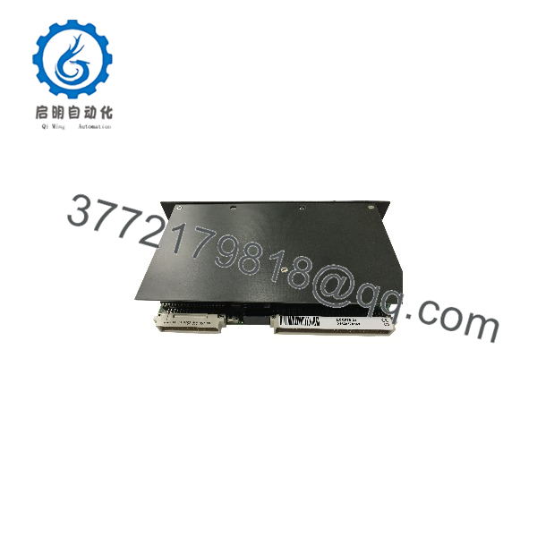
ECCP70-01
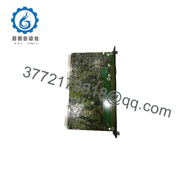
ECCP70-01
Installation & Configuration Guide
Stage 1: Pre-Installation Preparation — Approximately 5–10 Minutes
⚠️ Safety First
- Notify operations and obtain an approved maintenance window.
- Place the controlled equipment in a documented safe state.
- Apply lockout/tagout (LOTO) before removing the CPU.
- Isolate the applicable rack power.
- Wait at least 5 minutes for stored energy to discharge, then verify the supply is de-energized with a suitable meter.
Tools Required
- ESD wrist strap and grounded ESD work surface
- PH1 screwdriver
- Calibrated multimeter
- Wire labels
- Smartphone or camera for configuration photographs
- Approved terminal screwdriver appropriate to the installed hardware
Data Backup
- Save the current PLC/application program using the available B&R programming environment.
- Record the existing CPU identification and hardware configuration.
- Photograph the CPU, rack position, terminal wiring, connectors, and all switches/jumpers.
- Record serial-interface settings and any external communication configuration.
- Confirm whether the existing system uses a separate application-memory module. ECCP70-01 documentation specifies that this memory module is ordered separately.
Stage 2: Removing the Old Module — Approximately 5 Minutes
- Remove the front bezel or protective cover where applicable.
- Label every removable connection before disconnecting it.
- Disconnect wiring without pulling on individual conductors.
- Release the rack/module locking mechanism.
- Pull the CPU straight out to avoid damaging the backplane connector.
- Inspect the module connector and rack backplane for bent contacts, contamination, corrosion, or mechanical damage.
- Keep the removed CPU beside the work area until commissioning is complete.
⚠️ Do not discard the old ECCP70-01 yet. Its switch positions, memory-module arrangement, labels, and hardware revision may provide information that is not captured in the software backup.
Stage 3: Installing the New Module — Approximately 5–10 Minutes
- Connect the ESD wrist strap before handling the replacement CPU.
- Verify the complete part number: .
- Compare the replacement against the removed unit before insertion.
- Check the application-memory arrangement. The CP70 documentation specifies separate application program memory hardware.
- Replicate documented configuration settings from the original installation.
- Pay particular attention to serial-interface configuration and any node-address or termination settings associated with the installation.
- Insert the CPU straight into the rack.
- Confirm full mechanical seating and engage the locking mechanism.
- Reconnect wiring according to the original photographs and approved wiring documentation.
- Check each connection before applying power.
Self-Checklist
- Correct part number
- Application-memory configuration verified
- Switch/jumper configuration copied
- Wiring labels checked
- Connectors fully seated
- Rack locking mechanism engaged
- No foreign material inside the rack
Stage 4: Power-On & Testing — Approximately 10 Minutes
- Before energizing, check the relevant supply rails for shorts.
- Power the rack while keeping field equipment in the approved safe condition.
- Observe the CPU status indicators and compare them with the documented normal operating state.
- Establish communication with the installed B&R programming environment.
- Verify that the replacement CPU initializes correctly.
- Confirm the application program and memory arrangement.
- Check serial communications before returning the machine to automatic operation.
- Perform a controlled dry run.
- Verify critical inputs, outputs, interlocks, alarms, and permissives.
- Return the equipment to production only after the control sequence passes the approved functional test.
⚠️ Troubleshooting Note: If the replacement does not communicate, do not immediately assume the CPU is defective. Check the application-memory module, programming environment, serial-interface configuration, rack compatibility, and hardware revision first. uses a legacy CP70 architecture, so modern PLC engineering assumptions do not necessarily apply. Historical documentation identifies B&R PROgramming SYStem as the programming environment for .
Frequently Asked Questions (FAQ)
Can I hot-swap the B&R ?
Do not assume hot-swapping is permitted. is a legacy MULTI/MIDI rack CPU, and the available documentation does not establish it as a hot-swappable module. For a planned replacement, isolate rack power, follow the site’s LOTO procedure, and remove the CPU only after verifying the rack is de-energized.
Is the obsolete?
Yes. Current secondary-market documentation identifies the as discontinued, while B&R’s current product database still provides a technical product entry for the part number.
That distinction matters. A current database entry does not mean the CPU belongs to a current-generation automation platform. Treat as a legacy maintenance part and verify stock condition before committing to a shutdown window.
Is a modern B&R Automation Studio CPU?
No. is a Type B MULTI CPU for the older MULTI/MIDI rack architecture. Historical documentation identifies B&R PROgramming SYStem for programming. Do not assume an Automation Studio project can simply be downloaded to this controller.
Will I lose the PLC program when I replace the CPU?
Not necessarily, but you must verify the application’s memory architecture first. The documentation explicitly states that its application program memory module is separate and must be ordered separately. If the installed system stores the application in a removable memory module, preserve and correctly transfer that hardware during replacement.
Back up the application before removing the original CPU whenever the existing programming environment and hardware permit it.
Does support RS232 and RS485?
Yes. B&R specifies an application interface supporting RS485/RS232/TTY. The RS485 interface is electrically isolated and network-capable, while RS232 is not electrically isolated. The CPU also has a separate TTY online interface with an electrically isolated receiver.
What should I verify before buying a replacement?
At minimum, verify:
- Exact part number:
- MULTI or MIDI rack compatibility
- Application-memory module configuration
- Existing serial-interface requirements
- Hardware revision and physical condition
- Availability of the programming environment required by the installed system
- Supplier’s stated condition — Factory Sealed, New Surplus, or Refurbished/Tested
- Actual warranty and test documentation supplied with the individual unit
For legacy hardware, I would not accept “compatible” as sufficient information. Match the exact CPU part number and confirm the surrounding rack and application-memory architecture before the maintenance window.



