
 WhatsApp: +86 16626708626
 Email:
  Phone: +86 16626708626
Description
Key Technical Specifications
- Material Number: ECPE84-1
- Product Designation: MULTI analog input module
- Input Channels: 8
- Input Signal: 0–10 VDC
- Resolution: 16 bit
- Channel Isolation: Isolated analog input channels
- Input Impedance: High-impedance voltage input
- Conversion Accuracy: Approximately ±0.1% of full scale, according to distributor data
- Installation: B&R MULTI system rack or compatible backplane
- Field Wiring: Use shielded signal cable; route analog wiring away from motor and switching cables
- Operating Temperature: Approximately −20 to +60 °C, according to distributor data
- Storage Temperature: Approximately −40 to +85 °C, according to distributor data
- Dimensions: Approximately 75 × 80 × 30 mm
- Weight: Approximately 150 g
- Signal Type: Voltage input only; do not assume 4–20 mA compatibility
- Replacement Note: B&R lists the base material number as ECPE84-1; ECPE84-1B may identify a revision or market-specific variant
B&R’s official product page identifies the ECPE84-1 family, while the “B” suffix appears in reseller and secondary-market listings. Confirm the module label, revision, and terminal assignment before treating ECPE84-1B as identical to every ECPE84-1 unit. cite
Product Introduction
The B&R ECPE84-1B is an analog input module in the B&R MULTI automation family. It acquires eight isolated 0–10 VDC signals from transmitters, sensors, drives, test equipment, or process instruments and transfers converted values to the host control system through the MULTI backplane.
Its 16-bit conversion resolution and isolated channels suit voltage-based process measurement where ground-potential differences can corrupt readings. This is not a universal analog module: verify the required 0–10 VDC range, rack compatibility, firmware support, and exact ECPE84-1 versus ECPE84-1B hardware revision before installation. cite
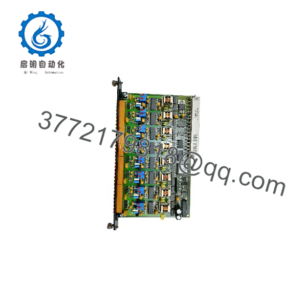
ECPE84-1B
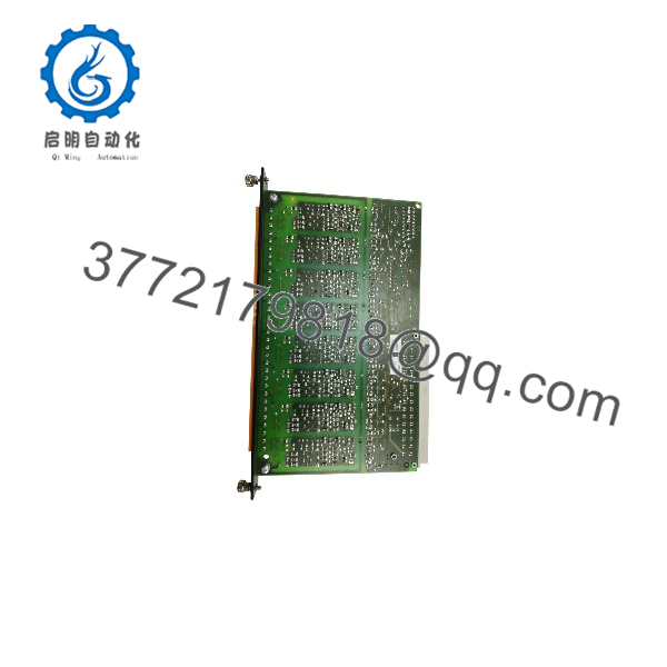
ECPE84-1B
Troubleshooting Quick Reference
| Symptom | Possible Cause | Relevance to This Part | Quick Check Method | Recommendation |
|---|---|---|---|---|
| Module is not recognized by the controller | Incorrect rack position, backplane fault, incompatible module, or damaged connector | ✅ High | Check the B&R diagnostic tree, module slot, seating, and backplane status | Power down, reseat the module, inspect contacts, and verify the configured hardware catalog |
| All eight channels read zero | Missing sensor supply, common wiring fault, incorrect input mode, or backplane communication failure | ⚠️ Medium | Apply a known 0–10 VDC test signal directly to one channel and verify the module diagnostic value | Test at the module terminals before replacing the card |
| One channel reads zero | Open signal wire, failed transmitter, damaged terminal, or failed input channel | ✅ High | Measure voltage at the transmitter and at the corresponding module input terminal | Repair field wiring first; replace the module only if a verified test voltage is not detected |
| Several channels read the same value | Shared common fault, incorrect reference wiring, or wiring short | ❌ Low | Measure each channel relative to the correct analog common and compare with the PLC value | Check the signal reference and terminal wiring before condemning the input card |
| Reading is higher than the transmitter output | Wrong scaling, common-reference error, or electrical noise | ❌ Low | Inject 0 V, 5 V, and 10 V with a calibrated source and compare raw counts with engineering values | Correct scaling and grounding; validate the channel using a known source |
| Reading is unstable | Shielding problem, ground loop, noisy 24 V supply, or cable routing near drives | ❌ Low | Substitute a short shielded test lead and calibrated voltage source | Separate analog wiring from motor cables and terminate shielding according to the B&R installation guide |
| Channel saturates near full scale | Input above 10 VDC, wrong sensor range, or wiring error | ✅ High | Measure the actual channel voltage with a calibrated multimeter | Remove the overvoltage source immediately; do not apply more than the specified input range |
| Channel value is negative or inverted | Reversed signal/reference wiring or incorrect application scaling | ❌ Low | Measure signal polarity directly at the terminal and inspect the software scaling | Correct wiring and scaling; a voltage input should not be treated like a current loop |
| Intermittent faults during machine operation | Vibration, loose connector, EMC interference, or backplane contact problem | ⚠️ Medium | Monitor diagnostics while flexing the cable and inspecting the module latch and rack contacts | Secure wiring, correct shielding, and inspect the rack before replacement |
| Input accuracy changed after replacement | Different revision, calibration data, scaling, or incompatible module variant | ✅ High | Compare the replacement label, hardware revision, raw counts, and configuration file | Match the exact revision and recalibrate or validate all eight channels |
| Controller reports a module configuration error | ECPE84-1B is not supported in the loaded hardware configuration | ✅ High | Compare the engineering project’s module identifier with the installed nameplate | Update the hardware configuration only after confirming OEM compatibility |
| No change after applying a known test voltage | Failed input circuitry, terminal contact issue, or module power/backplane fault | ✅ High | Apply 0 V, 5 V, and 10 V from a calibrated source and monitor raw input values | If the source is verified and the channel remains fixed, replace or repair the module |
Do not connect a 4–20 mA transmitter directly to this module unless the exact B&R documentation confirms current-input support for that hardware variant. For troubleshooting, provide the module nameplate, revision, rack slot, raw channel values, applied test voltage, controller diagnostics, and wiring photographs.
Frequently Asked Questions (FAQ)
What is the B&R ECPE84-1B?
It is an eight-channel analog input module for the B&R MULTI automation system. The documented signal range is 0–10 VDC, with 16-bit conversion and isolated inputs.
Is compatible with B&R ECPE84-1?
The base material number is identified as , while appears as a suffix-marked market or revision variant in reseller listings. Do not assume complete interchangeability. Compare the label, hardware revision, connector layout, module identifier, and host-system compatibility before swapping units. cite
Can this module read 4–20 mA signals?
Do not assume that it can. Available specifications identify as a 0–10 VDC analog input module. A 4–20 mA signal normally requires a current-input module or an approved signal converter. Applying current directly can produce incorrect readings or damage the input circuit.
What should I check before ordering a replacement?
Confirm the B&R brand, marking, material number, revision, connector and terminal arrangement, MULTI rack type, eight-channel configuration, 0–10 VDC range, and required isolation. Request a clear photograph of the front label and rear connector if the listing does not show them.
Can I hot-swap the ?
Do not hot-swap it unless the exact B&R system documentation explicitly permits live module replacement. Isolate control power, follow the rack’s discharge procedure, and protect the module from ESD before removing it.
Will the PLC program need changes after replacement?
The application may not need changes if the replacement has the same hardware identity, revision compatibility, and configuration. Still, verify the hardware catalog, module address, channel scaling, filtering, diagnostics, and calibration values after installation.
Why is a surplus cheaper than a factory unit?
It may be unused project stock, discontinued inventory, refurbished equipment, or a used module. Ask the seller to state the condition precisely, provide the serial or revision marking, and explain the functional test performed. For a used analog card, request measured results from all eight channels—not just a power-on photograph.



