
 WhatsApp: +86 16626708626
 Email:
  Phone: +86 16626708626
Description
Key Technical Specifications
| Parameter | Value |
|---|---|
| Manufacturer | B&R Industrial Automation |
| Part Number | ECPNC3-0 |
| Product Family | PNC3 |
| System Family | B&R MULTI / MIDI / M264 |
| Module Type | Counter / positioning module |
| Encoder Channels | 1 |
| Counter Resolution | 24 bit |
| Encoder Type | Incremental encoder |
| Encoder Input | Asymmetric |
| Encoder Supply | Externally supplied 24 VDC |
| Maximum Counting Frequency | 200 kHz in historical PNC3 documentation |
| Current B&R Listing Frequency | 50 kHz |
| Analog Output | ±10 V |
| Analog Output Resolution | 11 bit |
| Encoder Signal Inputs | A, B, Reference (R) |
| Input Isolation | Galvanically isolated through optocouplers |
| Rack Installation | MULTI, MIDI, and M264 racks |
| Power Consumption at +8 V | 1.2 W |
| Power Consumption at +15 V | 0.4 W |
| Power Consumption at −30 V | 0.6 W |
Important frequency note: Available documentation gives two different maximum-frequency figures. Historical PNC3 documentation specifies 200 kHz, while a current B&R product-data listing reproduced by distributors identifies 50 kHz for ECPNC3-0. For a high-speed encoder application, verify the exact hardware revision and operating mode against the applicable B&R documentation before designing around either figure.
The ECPNC3-0 and ECPNC3-1 are not interchangeable simply because they share the PNC3 family designation. The documented ECPNC3-0 architecture is intended for externally supplied 24 VDC encoders, while ECPNC3-1 uses a different encoder-supply/input arrangement.
Product Introduction
The B&R ECPNC3-0 PNC3 is a legacy counter and positioning module for B&R MULTI, MIDI, and M264 control systems. It processes one incremental encoder channel with 24-bit counting and provides a ±10 V analog output. The ECPNC3-0 is designed around an externally supplied 24 VDC encoder interface.
This module is mainly relevant to maintaining existing B&R motion and positioning equipment rather than designing a new control system. The encoder input uses galvanic isolation, and the PNC3 architecture supports encoder-based position measurement and counting without replacing the existing legacy rack.
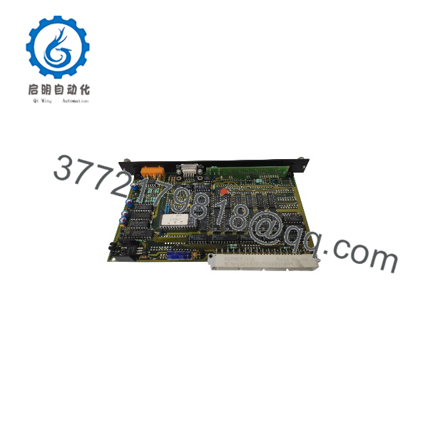
ECPNC3-0 PNC3
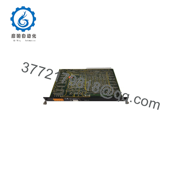
ECPNC3-0 PNC3
Installation & Configuration Guide
Stage 1: Pre-Installation Preparation — Approximately 5–10 Minutes
⚠️ Safety First
- Notify operations and establish the approved maintenance window.
- Put the machine into its documented safe state.
- Apply lockout/tagout (LOTO) before removing the module.
- Isolate the applicable B&R rack power.
- Wait at least 5 minutes for stored energy to discharge.
- Verify the rack supply is actually de-energized with a suitable multimeter.
Tools Required
- ESD wrist strap
- Grounded ESD work surface
- PH1 screwdriver where applicable
- Calibrated multimeter
- Wire labels
- Smartphone or camera
- Appropriate terminal screwdriver
Data Backup
- Save the current PLC/application configuration using the installed B&R programming environment.
- Photograph the complete installation before touching the wiring.
- Photograph the encoder connector and terminal arrangement.
- Record encoder manufacturer, model, supply voltage, and signal type.
- Record the existing analog-output wiring.
- Confirm whether the machine uses A/B quadrature signals plus a reference pulse.
- Record the existing module identification and hardware markings.
Stage 2: Removing the Old Module — Approximately 5 Minutes
- Remove the applicable front cover or protective hardware.
- Label all encoder and analog connections before disconnecting them.
- Disconnect the wiring carefully. Do not pull directly on the cable.
- Release the rack/module retaining mechanism.
- Pull the straight out of the rack.
- Inspect the backplane connector for contamination, bent contacts, or mechanical damage.
- Inspect the removed module’s connector and PCB for overheating or corrosion.
⚠️ Keep the original module until commissioning is complete. Its connector orientation, wiring arrangement, hardware markings, and physical configuration are valuable references if the replacement does not initialize correctly.
Stage 3: Installing the New Module — Approximately 5–10 Minutes
- Put on the grounded ESD wrist strap.
- Verify the replacement is specifically marked .
- Do not substitute an ECPNC3-1 based only on the family name.
- Verify the encoder supply arrangement. The is specified for an externally supplied 24 VDC encoder.
- Compare the encoder A, B, and reference-pulse wiring with the original photographs.
- Check signal polarity and common/reference connections.
- Insert the module straight into the correct rack position.
- Confirm complete seating before reconnecting wiring.
- Reconnect the encoder and ±10 V analog connections according to the approved wiring diagram.
- Check each connection mechanically before energizing the rack.
Self-Checklist
- Correct part number
- Correct module type
- External 24 VDC encoder supply verified
- A/B signals correctly identified
- Reference/R signal correctly identified
- Analog ±10 V wiring checked
- Module fully seated
- Retaining mechanism locked
- Wiring secured
Stage 4: Power-On & Testing — Approximately 10–15 Minutes
- Check the encoder supply and signal wiring for shorts before power-up.
- Energize the B&R rack while keeping the machine in a controlled safe state.
- Check the module status indication and rack response.
- Verify that the B&R control system recognizes the module correctly.
- Confirm the external encoder receives the expected 24 VDC supply.
- Rotate or simulate the encoder under controlled conditions.
- Verify A/B quadrature counting.
- Check the reference pulse when the application uses the R signal.
- Verify the expected count direction.
- Check the ±10 V analog output against the application’s scaling.
- Run a controlled machine test before returning the equipment to automatic operation.
⚠️ Troubleshooting Note: If the count direction is reversed, check the A/B phase relationship before changing software parameters. If counts intermittently disappear, inspect the encoder supply, cable shielding, connector contacts, and signal reference. If the module is not recognized, verify rack position and hardware compatibility before assuming the has failed.
Frequently Asked Questions (FAQ)
Can I hot-swap the B&R ?
Do not assume it is hot-swappable. The is a legacy rack-mounted module. Unless the machine’s B&R documentation explicitly permits energized module replacement for the specific rack configuration, power down and isolate the rack before removal.
Is the obsolete?
Yes. Multiple industrial automation parts databases identify as discontinued. That makes condition and traceability particularly important when sourcing a replacement.
For a critical production line, verify the physical part number and obtain clear photographs before purchasing surplus inventory.
Is the same as ECPNC3-1?
No. This is one of the most important replacement checks.
is designed for an externally supplied 24 VDC encoder with asymmetric input. Historical B&R documentation describes ECPNC3-1 separately, with a different encoder-supply and input arrangement.
Do not substitute the -1 variant simply because the connector and module dimensions appear similar.
What type of encoder does use?
It is intended for an incremental encoder, with A, B, and reference/R signals documented for the interface. The -0 variant uses an externally supplied 24 VDC encoder. The encoder inputs use galvanic isolation through optocouplers according to historical B&R documentation.
Before installation, verify the encoder’s voltage, current consumption, signal configuration, and wiring against the original machine documentation.
What is the maximum counting frequency?
This requires caution. Historical documentation specifies 200 kHz, while current distributor data based on B&R product information lists 50 kHz for .
For an existing machine operating near either limit, do not rely on a generic catalog number. Verify the exact revision and applicable B&R technical documentation.
Does provide an analog output?
Yes. The module provides one ±10 V analog output, with historical documentation specifying 11-bit resolution. This output is separate from the incremental encoder counting function and should be checked against the machine’s original scaling and control configuration.
Why is the replacement price different between suppliers?
With a discontinued B&R module, price differences often reflect condition and testing status, not simply the part number. Current listings show separate categories such as never-used original packaging, never-used repackaged units, and refurbished units.
For a production replacement, ask the supplier to state the exact condition in writing: Factory Sealed, New Surplus, or Refurbished/Tested. For refurbished stock, request the test scope, photographs of the actual unit, warranty period, and confirmation that the encoder interface and analog output were tested.



