WhatsApp: +86 16626708626
 Email:
 Phone: +86 16626708626
Description
Core Product Summary (Brand / Model / Key Attributes)
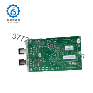
The B&R X20AT2222 is an analog temperature input slice I/O module belonging to the B&R X20 automation system family. Designed for precise temperature acquisition, this module converts signals from resistance temperature detectors into digital values for control systems connected via X2X Link or fieldbus controllers.
This module features two configurable inputs for Pt100 and Pt1000 sensors as well as direct resistance measurement. It offers 16-bit digital converter resolution with a temperature measurement resolution of 0.1°C. Each channel can be configured independently for 2-wire or 3-wire connections with a constant current supply. Operating over a sensor measurement range of -200.0°C to +850.0°C, the module includes a 1st-order low-pass input filter with a cutoff frequency of 500 Hz, configurable filter times, integrated sensor signal monitoring, and 500 Vrms isolation between channels and the system bus.
Key Technical Specifications
| Parameter | Technical Specification |
| Brand & Order Number | B&R X20AT2222 |
| Product Type | Analog RTD / Temperature Input Module |
| System Family | B&R X20 System |
| Number of Inputs | 2 analog inputs |
| Supported Sensor Types | Pt100, Pt1000, direct resistance measurement |
| Wiring Configuration | Configurable 2-wire or 3-wire connections per module |
| Digital Converter Resolution | 16-bit |
| Temperature Resolution | 0.1°C (1 LSB = 0.1°C) |
| Temperature Measurement Range | -200.0°C to +850.0°C (Pt100 / Pt1000 per EN 60751) |
| Resistance Measurement Range | 0.1 to 4500 Ω (G = 1) / 0.05 to 2250 Ω |
| Measurement Principle / Sensor Supply | Constant current supply (250 µA ±1.25%) |
| Conversion Procedure | Sigma-Delta |
| Input Filter | 1st-order low-pass filter, cutoff frequency 500 Hz |
| Configurable Filter Time | 1 ms to 66.7 ms |
| Isolation Voltage | 500 Vrms between channels and system bus |
| Bus Power Consumption | Internal I/O: 1.1 W (0.01 W bus power consumption) |
| Status Indicators | Diagnostics LED (r/e), channel status LEDs (1–2) |
| Operating Temperature Range | -25°C to +60°C (horizontal), -25°C to +50°C (vertical) |
| Degree of Protection | IP20 |
Detailed Product Overview
The B&R X20AT2222 serves as a specialized analog input module within the B&R X20 I/O series, specifically engineered to interface resistance-based temperature sensors directly with PLCs, industrial PCs, and distributed control architectures. By processing signals from standard Pt100 and Pt1000 platinum RTD sensors, the module provides direct digitized temperature data to the controller over the backplane bus, eliminating the need for external signal transmitters.
Each input channel utilizes a 16-bit Sigma-Delta analog-to-digital converter paired with a constant current supply of 250 µA to minimize self-heating in connected sensors. Signal evaluation covers the entire standard sensor range from -200.0°C to +850.0°C with 0.1°C digital resolution. For applications requiring direct impedance evaluation, the channels can be switched to direct resistance measurement mode with a range up to 4500 Ω.
The module supports both 2-wire and 3-wire connection schemes. Utilizing 3-wire connections compensates for lead wire resistance, ensuring accuracy over longer cable runs. Integrated diagnostic functions actively monitor each input signal for open-circuit line breaks, upper limit overflows, and lower limit underflows. A 1st-order low-pass hardware filter with a cutoff frequency of 500 Hz, combined with programmable digital filter times between 1 ms and 66.7 ms, reduces high-frequency electrical noise and power line interference.
Designed as a three-part modular slice, the X20AT2222 electronic module snaps into a compatible X20 bus module (such as the X20BM11) and connects to field wiring via a removable terminal block (such as the 6-pin X20TB06). This construction permits hot-swapping of the electronic component without disturbing the backplane bus or field wiring harness.
X20AT2222
X20AT2222
Engineering Selection Highlights
- Dual RTD Sensor Support: Configurable per channel for both Pt100 and Pt1000 sensors, allowing flexible mixed-sensor deployments on a single slice.
- Integrated Lead Compensation: Configurable 3-wire mode eliminates measurement errors caused by long field cable resistance without extra hardware.
- 0.1°C Native Resolution: High-precision 16-bit Sigma-Delta converter provides standardized 0.1°C output values directly to control registers.
- Direct Resistance Mode: Operates up to 4500 Ω for non-standard resistance sensors or potentiometer feedback processing.
- Comprehensive Signal Diagnostics: Automated line-break detection and limit monitoring report clear error flags to the CPU register.
- Noise Mitigation: Built-in 500 Hz hardware filter plus configurable digital filtering times ensure stable process readings in electrically noisy panel environments.
System Compatibility & Integration Requirements
| Item / Dependency | Verified Compatibility or Requirement | Practical Note |
| System Family | B&R X20 System | Connects to X2X Link backplane |
| Required Bus Module | X20BM11 or X20BM15 | Serves as base carrier and internal I/O power supply jumper |
| Required Terminal Block | X20TB06 (6-pin) or X20TB12 (12-pin) | Push-in or screw terminal options for field wiring |
| Configuration Software | B&R Automation Studio | Configures sensor type, filter times, and operating mode per channel |
| Operating System / Firmware | Compatible with X22/X2X bus controllers | Automatic firmware updates via controller bus |
Dimensions, Mounting & Connection Notes
- Mounting Method: Direct insertion into an X20 bus module mounted on a standard 35 mm DIN rail (EN 60715).
- Physical Structure: Modular slice comprising base module, electronic module, and removable terminal block.
- Terminal Block Options: Standard 6-pin terminal block (X20TB06) or 12-pin terminal block (X20TB12).
- Terminal Pinout:
- Pin 1: Sensor + Channel 1
- Pin 2: Sense – Channel 1
- Pin 3: Sensor – Channel 1
- Pin 4: Sensor + Channel 2
- Pin 5: Sense – Channel 2
- Pin 6: Sensor – Channel 2
- Wiring Scheme:
- 3-wire connection: Uses Sensor+, Sense-, and Sensor- pins for lead compensation.
- 2-wire connection: Uses Sensor+ and Sensor- pins; unused channels must be disabled in software.
- Degree of Protection: IP20, intended for installation inside an enclosure meeting protective requirements.
- Operating Orientation: Horizontal orientation supports ambient temperature up to 60°C; vertical orientation requires derating to 50°C.
FAQ
What is the B&R X20AT2222?
The B&R X20AT2222 is a 2-channel analog temperature input module for the B&R X20 I/O system, designed for measuring resistance temperature sensors such as Pt100 and Pt1000.
Which sensor types are supported by the X20AT2222?
The module supports Pt100 and Pt1000 platinum resistance sensors as well as direct resistance measurement up to 4500 Ω. Sensor types are configurable per channel.
Does the X20AT2222 support 3-wire RTD connections?
Yes, the module supports both 2-wire and 3-wire wiring configurations per module, allowing automatic lead-wire resistance compensation in 3-wire mode.
What is the measurement resolution of the X20AT2222?
The module uses a 16-bit analog-to-digital converter delivering a temperature resolution of 0.1°C (1 LSB = 0.1°C) across a temperature measurement range of -200.0°C to +850.0°C.
What base modules and terminal blocks are required for the X20AT2222?
The module requires an X20 bus module (such as the X20BM11 or X20BM15) and a 6-pin or 12-pin X20 terminal block (such as the X20TB06 or X20TB12).
How does the X20AT2222 indicate error states?
The module features status LEDs: a green ‘r’ LED for run mode, a red ‘e’ LED for general module/channel errors, and channel status LEDs (1–2) that flash during open line, overflow, or underflow conditions.
Verification & Troubleshooting Notes
- Channel Diagnostic LEDs (1–2 Blinking): Indicates an open line (sensor wire break), upper measurement limit overshoot, or lower limit undershoot on the corresponding channel. Check field wiring continuity and RTD connections.
- Module Error LED ‘e’ Solid Red: Indicates a module error, invalid operating mode, or system reset status. Verify configuration parameters in Automation Studio.
- Module LEDs ‘e’ + ‘r’ (Red On / Green Flash): Indicates invalid firmware on the module. Reload module hardware upgrades or re-flash firmware via the controller.
- Unexpected Temperature Offsets in 2-Wire Mode: Wire resistance is included in 2-wire measurements. Convert wiring to 3-wire mode or apply offset compensation in software registers.
- Value 0x8000 in Data Register: Represents an initial or invalid conversion value (e.g., prior to the first completed conversion cycle or during mode transitions).
- Unused Channels: Channels that are not connected to a sensor should be explicitly disabled in the system configuration to prevent open-circuit diagnostic error flags.