
 WhatsApp: +86 16626708626
 Email:
  Phone: +86 16626708626
Description
Key Technical Specifications
| Parameter | Specification |
|---|---|
| Manufacturer | CEAG Sicherheitstechnik GmbH |
| Product family | 1/942 / 2/942 Switch Amplifier |
| Model family | GHG 122 |
| Mounting | DIN rail |
| Input | NAMUR, mechanical contact, or optocoupler |
| Channels | 1 or 2, depending on order code |
| Output type | Relay on 2/942 variants |
| Relay contact rating | 250 VAC / 100 VDC |
| Maximum relay current | 5 A AC / 2 A DC |
| Maximum relay power | 100 VA / 50 W |
| Mechanical life | 10 million operations |
| Ambient temperature | -20°C to +60°C |
| Relative humidity | <95%, non-condensing |
| Typical supply options | 230 VAC, 120 VAC, 24 VAC, or 24 VDC depending on suffix |
| Explosion protection | EEx ia/ib on specified versions |
| ATEX certificate | TÜV 97 ATEX 1169 for documented 2/942 versions |
The CEAG technical sheet identifies the 2/942 as a switch amplifier with relay output. It accepts NAMUR inputs, mechanical contacts, or optocouplers, provides galvanic isolation between input, output, power supply, and contacts, and supports one- or two-channel configurations.
For example, GHG 122 3121 D 1009 is listed as a two-channel, 24 V version with EEx ia/ib protection, while GHG 122 3121 D 1002 is the corresponding two-channel 230 V version.
Product Introduction
The CEAG GHG122 is a legacy switch-amplifier platform used to interface field switching devices with control-system circuitry, particularly where intrinsic-safety isolation is required. The documented 1/942 and 2/942 versions support NAMUR sensors, mechanical contacts, or optocouplers and mount on a DIN rail.
The exact GHG122 suffix determines the electrical configuration. Two-channel relay-output versions provide galvanic isolation and relay contacts rated up to 250 VAC/5 A or 100 VDC/2 A. This makes the complete order code critical when replacing an installed unit.
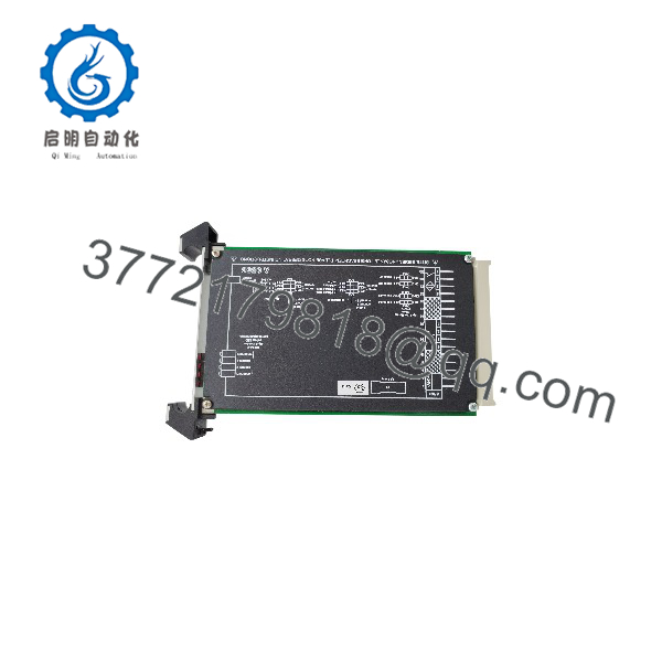
GHG122
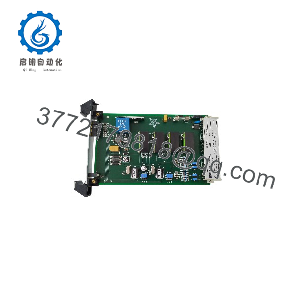
GHG122
Installation & Configuration Guide
Step 1 — Identify the Complete Order Code
Before replacement, record the entire label rather than ordering from GHG122 alone.
Check for:
GHG 122- 1/942 or 2/942 designation
- Channel count
- Voltage suffix
D1002,D1003,D1007,D1009, or another suffix- Ex certification markings
- Terminal arrangement
- Any installed DIP-switch configuration
Warning: A 230 VAC and 24 VDC GHG122 may have very similar physical appearances but cannot be treated as interchangeable.
Step 2 — Record the Existing Wiring
- Shut down the affected control loop according to the plant procedure.
- Isolate the module’s supply voltage.
- Verify absence of hazardous voltage.
- Photograph the terminal wiring.
- Record each input and output terminal.
- Record the connected sensor type.
- Record relay contact destinations.
- Note any line-monitoring configuration.
For Ex installations, verify the complete intrinsic-safety circuit against the approved system documentation before making wiring changes.
Step 3 — Remove the Existing Module
- De-energize the module.
- Confirm the correct circuit has been isolated.
- Disconnect field wiring and label each conductor.
- Remove the module from the DIN rail.
- Inspect the terminals and wiring for heat damage or corrosion.
- Compare the removed unit with the replacement.
Step 4 — Install the Replacement
- Verify the exact GHG122 order code.
- Confirm the supply voltage.
- Confirm one- versus two-channel configuration.
- Confirm the input type.
- Confirm the required Ex protection level.
- Mount the module on the DIN rail.
- Reconnect the wiring according to the original approved diagram.
- Verify terminal torque and conductor retention.
- Check separation between intrinsically safe and non-intrinsically safe circuits.
Step 5 — Commission the Signal Loop
- Apply the correct supply voltage.
- Verify the module’s operating indication.
- Activate each connected field device individually.
- Confirm the corresponding relay output changes state.
- Check the PLC/DCS input.
- Test the circuit with the field device in both normal and fault conditions.
- Verify line monitoring where the particular GHG122 variant supports it.
- Record the final test results.
Engineering Replacement Warning
The CEAG documentation specifies galvanic isolation between input, output, power supply, and contacts for the relevant switch-amplifier design. Do not bypass this isolation by modifying the wiring or substituting a non-approved interface.
FAQ
What is the CEAG ?
is the order-code family used for CEAG switch-amplifier equipment. Documented variants include the 1/942 and 2/942 switch amplifiers, used to interface NAMUR sensors, mechanical contacts, and related switching devices with control systems.
Is an intrinsically safe module?
Specified variants are certified for intrinsically safe applications. The CEAG certificate TÜV 97 ATEX 1169 covers the documented 2/942 electronic switch amplifier, including order codes in the family.
The certification must be checked against the exact complete order code before use in a hazardous-area installation.
What is the difference between 1/942 and 2/942?
The CEAG catalog identifies both as switch-amplifier variants. The 2/942 is specifically documented with relay output, while the 1/942 family includes configurations for switching-amplifier applications. The complete order code should be checked rather than identifying the module by the family number alone.
What does GHG 122 3121 D 1009 mean?
This is a specific order code for a documented two-channel, 24 V switch-amplifier configuration with EEx ia/ib protection. The CEAG technical documentation lists it among the 2/942 ordering options.
Is CEAG obsolete?
Specific variants are identified as discontinued by the manufacturer in current industrial replacement listings. For example, GHG 122-3121B1009 is listed as discontinued, while used and surplus units remain available through specialist suppliers.
Can be replaced by an MTL module?
Some suppliers identify specific variants with MTL replacement references. For example, one supplier lists as replaced by MTL5513 and GHG1223121 C1009 as replaced by MTL5516C.
However, a replacement should be selected based on the complete order code, input/output function, power supply, channel configuration, and hazardous-area certification, not simply because both devices are described as switch amplifiers.
What information should be provided when purchasing a replacement?
Provide a photograph of the complete nameplate and terminal side, including the full order number, voltage suffix, 1/942 or 2/942 designation, Ex markings, and revision/serial information. This avoids confusing electrically different variants within the family.



