
 WhatsApp: +86 16626708626
 Email:
  Phone: +86 16626708626
Description
Key Technical Specifications
- Manufacturer: CONSEN
- Model Number: FTA-6M
- Reported Revision: R1.SW2/3
- Product Category: Safety-system field termination assembly / field interface module
- Primary Function: Connects field-side safety-instrument wiring to internal controller or I/O-system cabling
- System Role: Field termination and marshalling hardware; not confirmed as an active safety logic solver
- Application Area: Safety instrumented system cabinets and related process-safety field I/O applications
- Field Connections: Exact terminal assignment, channel count, signal type, and supply distribution are configuration-dependent
- Controller Interface: Verify the mating cable, I/O card, controller family, and cabinet drawing before replacement
- Communications: No verified protocol specification is available for the FTA-6M hardware itself; do not assume Modbus, Ethernet, or other fieldbus capability from generic reseller listings
- Power Requirement: Not verified from an OEM datasheet; confirm exact supply, polarity, fuse rating, and grounding from the installed cabinet documentation
- Mounting: Confirm panel dimensions, terminal orientation, connector type, and grounding arrangement from the physical assembly
- Replacement Requirement: Match the full
FTA-6Mlabel,R1.SW2/3revision where applicable, terminal layout, mating I/O hardware, cable assembly, and approved safety-system documentation - Lifecycle Status: Treat as legacy/specialized safety hardware; stock, revision, and configuration must be verified before purchase
Public search results identify the item as a CONSEN FTA-6M safety instrumentation system component with a reported R1.SW2/3 reference, but no OEM technical datasheet was located that validates electrical ratings, channel count, safety integrity level, controller compatibility, or communications protocol. The available evidence supports describing it cautiously as a safety-system field termination/interface assembly, not as a standalone safety controller.
Product Introduction
CONSEN FTA-6M is a specialized field termination and interface assembly used in a safety instrumented system cabinet. It organizes field-side safety wiring and provides the connection path between sensors, final elements, marshalling terminals, and the corresponding internal safety I/O or controller cabling.
This is not a generic PLC module and should not be substituted by appearance alone. The FTA-6M label and reported R1.SW2/3 revision must match the existing termination arrangement, controller interface, cable set, and approved safety documentation. No verified OEM public datasheet was found, so electrical and functional compatibility must be confirmed from the installed system records.
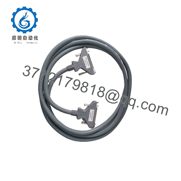
FTA-6M
Troubleshooting Quick Reference
| Symptom | Possible Cause | Relevance to This Part | Quick Check Method | Recommendation |
|---|---|---|---|---|
| Safety-system I/O shows no field signal | Open field cable, failed transmitter/switch, blown field fuse, incorrect bypass state, loose FTA terminal | ✅ Medium | Review the safety-system diagnostic screen; measure the field signal at the designated FTA terminal and compare it with the I/O-side connection using an approved meter | Verify field device, loop power, fuse, and wiring before replacing . |
| Multiple adjacent channels fail together | Common field power loss, loose multicore connector, damaged cable harness, shared fuse issue, termination assembly fault | ✅ High | Check common supply and return terminals, shared fuses, cable harness retention, and terminal torque; compare failed channels with the wiring drawing | Investigate common wiring and power first. Replace only after a controlled continuity test confirms an internal or terminal-path fault. |
| Safety input remains in trip state | Open-circuit detection operating correctly, field device fault, wrong contact wiring, bypass not restored, incorrect channel configuration | ✅ Medium | Confirm actual field contact state, check loop continuity, inspect bypass switches, and review input diagnostics | Do not force or jumper a safety input to clear a trip. Correct the field cause and follow the approved proof-test procedure. |
| Output command is present but final element does not move | Field fuse open, solenoid/relay failure, output I/O fault, wiring break, failed final element, FTA terminal issue | ✅ Medium | Under approved test conditions, measure output voltage at the I/O side and field side of the FTA; check solenoid coil resistance and field fuse | Separate controller output, termination path, field wiring, and final-element faults before ordering the FTA. |
| Intermittent fault appears during vibration or cabinet-door movement | Loose terminal, damaged conductor, poor cable strain relief, cracked solder joint, connector not latched | ✅ Medium | Inspect terminal clamp engagement, cable strain relief, connector latches, and wire ferrules with the system in a safe approved state | Repair terminals and wiring first. Replace the assembly if the fault follows the FTA in a controlled test. |
| Replacement unit physically fits but signals are wrong | Different revision, changed terminal pinout, incorrect mating cable, wrong channel allocation, wiring transferred by memory | ✅ High | Compare every terminal number, wire marker, connector key, and revision label with the old unit and approved drawings | Stop work. Do not energize until an independent checker verifies point-to-point wiring. |
| Safety controller reports internal I/O fault | Active safety I/O card fault, controller fault, backplane issue, configuration mismatch | ❌ Low | Review controller diagnostic logs, I/O card LEDs, rack power, and safety application diagnostics | Do not replace based only on an internal I/O fault. Diagnose the active I/O hardware first. |
| Visible heat damage, corrosion, or terminal discoloration | Overcurrent, loose connection, moisture ingress, chemical contamination, incorrect field wiring | ✅ High | Isolate power; inspect all terminals and conductor insulation; measure continuity and check for unintended shorts using OEM-approved methods | Replace damaged hardware and correct the source of heat, moisture, or overcurrent before restoring the safety function. |
| System fault occurs after maintenance | Bypass left active, field wires swapped, shield/ground connection changed, terminal not fully tightened, safety configuration altered | ✅ High | Perform point-to-point verification against approved drawings; review bypass register and maintenance log; inspect all work performed | Use a formal restoration and proof-test checklist. Do not return the SIF to service until the required validation is complete. |
❗ Safety-function warning: is associated with safety instrumentation. Do not bypass, jumper, force, or alter a safety input/output merely to restore production. Any work affecting a safety instrumented function requires the site’s approved management-of-change, bypass authorization, lockout/tagout, and proof-test process.
❗ Revision warning: The reported R1.SW2/3 reference may identify a revision or configuration state. Treat it as procurement-critical until verified. A termination assembly with a different revision can have a different terminal assignment, cable interface, grounding method, or approved application.
❗ Terminal-layout warning: Take clear, high-resolution photos of both sides of the old assembly before removal. Capture labels, terminal numbers, wire markers, jumpers, earth terminals, cable connectors, and the mating I/O card. It is the most common rookie mistake, but it happens constantly: someone moves wires by visual position rather than terminal identifier.
❗ Field-power warning: A failed safety output often comes from an external fuse, interposing relay, solenoid coil, or field power supply—not the termination assembly. Measure the voltage on both sides of the FTA under approved conditions before replacing it.
❗ Shielding warning: Follow the approved safety-system grounding and shield-termination scheme. Do not add ground links or bond cable shields at both ends simply because it “looks better.” A ground-loop or misapplied shield can introduce noise and create intermittent diagnostic faults.
❗ ESD warning: Use a grounded wrist strap and ESD-safe handling when the work includes mating safety I/O electronics. I have seen a technician diagnose a loose terminal correctly, then damage the active I/O card while handling it without ESD protection. The second fault was harder to find than the first.
Keep these checks in mind and you will save yourself 90% of typical rework time. If you need technical support, provide photos of the full label, revision marking, terminal layout, mating cable connectors, associated safety I/O module, cabinet drawing, point list, active diagnostics, and maintenance/proof-test records.
Frequently Asked Questions
What is the CONSEN ?
CONSEN is a specialized safety-system field termination or interface assembly. It is used to organize and connect field-side sensor and final-element wiring to internal safety I/O or controller cabling. Available public listings identify it as a safety instrumentation system component and reference R1.SW2/3, but they do not provide enough OEM data to verify the complete electrical or functional specification.
For that reason, describe and procure it as a configuration-dependent safety termination assembly, not as a confirmed standalone safety PLC, logic solver, or general I/O module.
Is a safety controller?
There is no verified public OEM evidence that itself is the active safety controller or logic solver. The available product wording supports a field-termination/interface role. The logic solver, safety I/O module, power distribution, and field termination hardware may be separate components in the installed system.
Before ordering, identify the actual active safety controller and I/O card from cabinet labels and the approved cause-and-effect documentation.
Can I replace with a generic terminal block or marshaling panel?
No. Do not substitute a generic terminal block, PLC terminal module, or third-party marshalling panel unless the system designer has completed and approved an engineering change. Safety termination hardware can incorporate specific terminal allocation, fusing, isolation, grounding, connector keying, test points, and wiring paths that are part of the validated safety function.
A replacement that looks similar can create an undetected wiring error or defeat diagnostic coverage. For a safety-system repair, use the exact approved part or a formally approved engineered replacement.
Can I hot-swap the CONSEN ?
Do not hot-swap it. Treat any removal as safety-system maintenance requiring a planned shutdown or an approved bypass process. Field terminals can carry live 24 V DC loops, relay voltages, solenoid power, or hazardous-area interface signals. Removing the assembly may trip the process, prevent a trip, create a false input, or alter a final-element state.
To be honest, there is no shortcut here. Isolate the affected safety function according to the approved procedure, obtain operations approval, document bypasses, verify field state, de-energize where required, and perform a proof test after restoration.
Will replacing erase safety logic or configuration?
The itself is most likely termination/interface hardware rather than the component that stores safety application logic. However, a replacement can still cause a functional change if terminal assignments, jumpers, cable orientation, shielding, or the mating I/O path differ.
Before removal, record:
- Full
label and reportedR1.SW2/3revision - Associated safety controller and I/O-module part numbers
- Cabinet and rack position
- Terminal numbers, wire markers, cable connectors, earth points, and jumper positions
- Field-device tags, loop drawings, and cause-and-effect matrix
- Bypass register, active alarms, diagnostics, and proof-test status
- Field-power supply and fuse assignments
- Shield and grounding arrangement
After installation, perform the documented point-to-point verification and proof test before returning the safety instrumented function to service.
Why is a New Surplus cheaper than factory supply?
New Surplus hardware often comes from unused project spares, cancelled safety-system expansions, OEM cabinet-builder stock, distributor overstock, or warehouse releases. A lower price may reflect surplus sourcing or legacy status, not automatically a defect.
For safety-related equipment, price must not be the deciding factor. Request:
- Actual photos of the full
label and all revision marks - Photos of every terminal, connector, mounting point, and any factory labels
- Source traceability, including OEM packing documents or procurement records where available
- Confirmation of Factory Sealed, New Original / New Surplus, or Refurbished condition
- Evidence of no corrosion, cracked housing, heat discoloration, missing terminals, altered labels, or rework
- Written warranty, return terms, confirmed stock quantity, and dispatch lead time
- A written statement of what functional or continuity testing the supplier performed
Do not accept an untraceable used assembly for a safety application without a documented engineering review and site approval.
What test process should a supplier complete before shipping?
For an represented as New Original / New Surplus, a supplier should complete a traceable inspection process while avoiding tests that could alter or compromise the intended safety hardware:
- Inbound inspection and traceability: Verify the full part label, revision marking, source documentation, serial or lot data where present, packing condition, and OEM markings. Inspect for counterfeit labels, corrosion, scratches, cracked insulation, heat marks, UV yellowing, rework evidence, missing terminals, damaged connectors, or altered jumpers.
- Mechanical inspection: Check mounting points, terminal clamps, screws, connector keying, cable retention, earth terminals, labeling, and any removable links. Confirm that every terminal is secure and that no contacts are bent or contaminated.
- Point-to-point continuity verification: Use a calibrated Fluke 115 or equivalent low-energy continuity test method to verify documented intended paths and identify unintended shorts. Perform tests only against an approved terminal schedule or supplied schematic; do not assume the internal signal path from a generic product description.
- Mated fit check: Where a compatible approved safety I/O rack and mating harness are available, verify mechanical fit, connector engagement, keying, and non-energized continuity between the termination assembly and its mating hardware. Do not claim active safety-function validation without the correct complete system and approved procedure.
- Electrical testing: Apply powered functional testing only when the supplier has the exact OEM-supported test setup and documented procedures. Do not apply 500 V insulation-resistance or hipot tests indiscriminately; that can damage suppression components, isolation devices, or connected electronics.
- Configuration documentation: Photograph terminal layout, revisions, jumpers, connector positions, and labels. Disclose clearly whether the unit is blank, configured, or has an unknown prior application state.
- Final QC and packaging: Require quality-inspector sign-off, ESD-safe handling for associated electronics, terminal protection, sealed packaging, foam or bubble wrap, heavy-duty corrugated boxing, and a dated QC-passed label. Inspection photos, continuity records, and test documentation should be available upon request.



