
 WhatsApp: +86 16626708626
 Email:
  Phone: +86 16626708626
Description
Key Technical Specifications
| Parameter | Specification |
| Manufacturer | Teledyne DALSA (formerly Coreco Imaging) |
| Model Number | CR-GEN0-M6400R3 |
| Interface Bus | PCI Express (x1 or x4 lane configurations) |
| Camera Interface | Multi-channel Camera Link / GigE Vision hardware offload engine |
| On-Board Buffer Memory | 64 MB SDRAM frame buffer |
| Max Acquisition Rate | Up to 85 MHz pixel clock rate |
| Digital I/O | Opto-isolated inputs, TTL outputs for strobe and shaft encoder trigger |
| Operating Temperature | 0°C to +55°C (32°F to 131°F) |
| Storage Temperature | -20°C to +70°C (-4°F to 158°F) |
| Software Support | Teledyne DALSA Sapera LT, MIL, stemmer CVB |
| Power Requirement | +3.3V DC, +12V DC directly via PCIe slot backplane |
| Form Factor | Low-profile / standard height PCIe expansion card |
Product Introduction
The Teledyne DALSA CR-GEN0-M6400R3 is a specialized frame grabber and image acquisition board designed for high-speed industrial machine vision applications. Positioned between industrial cameras and the host IPC processing system, it handles image frame buffering, onboard pixel reformatting, and real-time trigger sync without consuming critical host CPU cycles.
Deploying this module in automated inspection lines—such as PCB AOI, semiconductor wafer inspection, or high-speed packaging sorting—ensures zero dropped frames during continuous production runs. Installing a replacement CR-GEN0-M6400R3 board restores vision system processing immediately, bypassing expensive PC motherboard upgrades or software re-licensing fees associated with migrating to newer frame grabber platforms.
Core Strategy 1: SOP Quality Transparency
To ensure our vision hardware performs flawlessly in high-speed automated environments, every CR-GEN0-M6400R3 card undergoes our 5-step hardware evaluation:
- Inbound Traceability & Visual Inspection
- Verification of OEM serial numbers, PCB batch codes, and hardware revision labels.
- Microscopic audit of edge connector gold fingers, surface-mount FPGA pins, and onboard memory ICs for mechanical scoring, corrosion, or thermal stress signs.
- Inspection of external connector shell threads and retention brackets.
- Live Functional Testing
- Installed into an industrial PC chassis equipped with an active PCIe bus and running 64-bit Windows OS with DALSA Sapera LT drivers.
- Power-On Self-Test (POST): Verification of PCI bus enumeration, BAR register mapping, and driver initialization.
- Full-Speed Image Acquisition Test: Connected to a simulated Camera Link pattern generator; acquired 100,000 continuous frames at maximum pixel clock speed to verify zero FIFO buffer overruns or DMA transfer errors over a 24-hour period.
- Generation of a bench diagnostic report documenting DMA throughput.
- Electrical Parameter Testing
- Bus Line Stability: Verified PCIe 3.3V and 12V power rail current draw using a Fluke 115 multimeter under full acquisition load.
- Opto-Isolator Verification: Tested trigger input lines with a 24V pulse generator to confirm opto-coupler signal isolation integrity.
- Firmware & Configuration Verification
- Read out onboard EEPROM device ID and hardware revision registers via Sapera diagnostic tools.
- Document and log firmware build parameters to match OEM system requirements.
- Final QC & ESD Packaging
- Lead inspector sign-off on the quality control routing card.
- Card cleaned with non-conductive electronic solvent and sealed inside an anti-static ESD shield bag.
- Boxed in high-density anti-static foam enclosure within a 200 lb test shipping carton.
Bench test reports and live driver detection logs are available upon request prior to shipment.
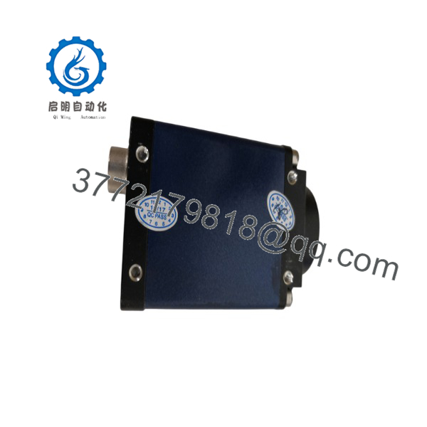
CR-GEN0-M6400R3
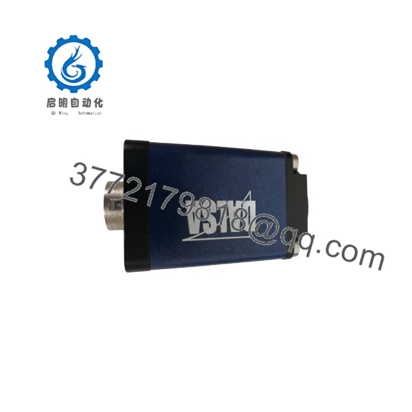
CR-GEN0-M6400R3
Troubleshooting Quick Reference
| Symptom | Possible Cause | Relevance to this Part | Quick Check Method | Recommendation |
| Board not detected in Windows Device Manager | PCIe bus slot dirty, power rail drop, or onboard FPGA failure | ✅ High | Re-seat card in another PCIe slot; check Device Manager for unknown PCI devices. | Clean edge fingers. If card fails to enumerate across multiple PCs, replace the board. |
| “Buffer Overflow” or dropped frames error | Host DMA transfer bottleneck or onboard SDRAM failure | 🟡 Medium | Run Sapera Buffer Diagnostic; verify PC motherboard PCIe power management is disabled. | If PC BIOS settings are optimized but memory parity errors persist in diagnostics, replace card. |
| No image trigger on external sensor signal | Opto-isolated input circuit blown by overvoltage | ✅ High | Apply 24V DC to trigger pins and read input status register via Sapera API. | If external encoder/sensor pulse is verified on scope but register stays low, replace board. |
| Image corruption / vertical line noise | Camera Link connector pin damage or receiver IC fault | ✅ High | Inspect MDR/SDR connector pins for bending; swap Camera Link cable. | If cable is good but acquisition shows fixed pattern noise across channels, replace card. |
| System freezes during acquisition start | Interrupt allocation conflict or corrupt driver allocation | 🟡 Medium | Update Sapera LT runtime; check for IRQ sharing in host operating system. | Reinstall drivers. If system hard-locks only on acquisition init, replace frame grabber. |
If vision diagnostics yield ambiguous errors, capture your Sapera Log Viewer output and consult our vision system engineering team before pulling the hardware.
Core Strategy 2: Technical Pitfall & Survival Guide
Replacing a machine vision frame grabber requires precise attention to hardware and driver parameters to prevent inspection line shutdown.
- PCIe Slot Lane & Power Allocation
- The Trap: Plugging the card into a slot that shares bandwidth with another high-speed expansion card, causing host DMA buffer starvation.
- Avoidance: Install the board into a dedicated PCIe slot wired directly to the CPU root complex rather than a multiplexed PCH slot.
- ❗ I’ve seen projects where a tech swapped a frame grabber card and experienced random dropped frames for a week, simply because the card was inserted into a shared PCIe slot. Check motherboard lane allocation first.
- Driver & Sapera LT Version Mismatch
- The Trap: Installing a replacement board with a different hardware revision (e.g., R3 vs R1) can cause initialization errors if using older Sapera SDK versions.
- Avoidance: Check the exact revision code suffix (
R3) on the PCB silkscreen and ensure your host PC runtime environment matches the revision’s supported driver package. - ❗ Don’t assume any driver package works. Verify the installed Sapera LT version supports the specific hardware revision before placing the board in service.
- Connector Pin Stress & Over-Torquing
- The Trap: Yanking high-density Camera Link or I/O cables can pull thumbscrew standoffs off the frame grabber’s bracket, ripping PCB solder pads.
- Avoidance: Hand-tighten connector thumbscrews evenly. Use strain-relief tie-downs on heavy industrial cable bundles within the IPC cabinet.
- ❗ It’s the most common rookie mistake in vision systems. Take the tension off the cable before screwing it in. Never use tools to tighten cable thumbscrews.
- Electrostatic Discharge (ESD)
- The Trap: Static discharge during installation can destroy exposed high-speed differential line receiver ICs connected directly to the IO ports.
- Avoidance: Wear a grounded wrist strap attached to the PC chassis ground before touching the board edge or removing it from its ESD bag.
- ❗ Handling an ungrounded card in a low-humidity plant can instantly zap the camera interface ICs. Always use proper ESD protection.
Following these deployment practices will save hours of troubleshooting and prevent premature card failure.
Frequently Asked Questions (FAQ)
Is the DALSA CR-GEN0-M6400R3 hot-swappable in a running PC?
No. Standard PCI Express architecture does not support hot-swapping frame grabber cards. Inserting or removing the card while the host computer is powered on will cause electrical shorts across the PCIe power pins, damaging the frame grabber, motherboard, or both. Always shut down the host PC and disconnect the main power cable before installation.
Do I need to re-license the Sapera LT software when replacing this card?
No. Teledyne DALSA Sapera LT runtime licenses for standard acquisition are tied to hardware identifiers on the frame grabber itself or run under a standard runtime license. Swapping a damaged CR-GEN0-M6400R3 card with a functional unit of the same model allows existing vision application software (such as Sherlock, VisionPro, or custom C++/C# applications) to run without re-licensing.
How do I back up my camera configuration files (.CCF) before replacing the card?
Camera configuration files are stored on the host PC hard drive rather than the frame grabber card itself (typically located in the Sapera CamFiles directory). Copy your specific .CCF configuration file to a backup folder or flash drive before swapping hardware so you can reload the exact camera timing parameters after board replacement.
What is the difference between standard acquisition cards and the?
The features specific hardware revisions (R3) incorporating updated FPGA timing logic and onboard memory controllers compared to older R1 or R2 variants. This provides improved DMA burst efficiency across modern PCIe bus controllers and updated firmware support for higher pixel clock rates.
Can this card supply power over Camera Link (PoCL) to my industrial cameras?
Compatibility depends on the specific jumper configuration and board variant. Standard CR- cards provide signal acquisition only, while specific sub-models include PoCL power delivery components. Verify whether your original card has PoCL jumper blocks installed near the front bracket before connecting PoCL-enabled cameras.



