
 WhatsApp: +86 16626708626
 Email:
  Phone: +86 16626708626
Description
Key Technical Specifications
| Parameter | Value |
| Main DC Bus Input Voltage | 24 to 80 V DC |
| Control Supply Voltage | 18 to 30 V DC |
| Continuous Output Current | 15 A |
| Peak Output Current (3 seconds) | 30 A |
| PWM Switching Frequency | 20 kHz |
| Feedback Interface | Incremental Encoder / Tachometer / Resolver |
| Command Interface | \pm 10 V Analog Signal / CANopen System Bus |
| Status Display | LED Diagnostics (POWER, DISABLED, FAILURE) |
| Protection Functions | Overvoltage, Undervoltage, Short Circuit, Thermal Overload |
| Cooling Method | Integrated Side-Mounted Forced-Air Cooling Fan |
| Mounting Orientation | Panel Mount with Heavy-Duty Heat Sink |
| Operating Temperature | 0 to +50 °C (+32 to +122 °F) |
Product Introduction & Supply Chain Strategy
The Danaher Motion FSA80 is a heavy-duty DC servo amplifier engineered specifically for low-voltage, high-torque applications such as Automated Guided Vehicles (AGVs), material handling systems, and battery-powered mobile robotics. Operating on a 24 to 80 V DC bus, the FSA80 provides precise PWM speed and torque regulation for brushed or brushless PMDC motors integrated with NDC AGV vehicle control architectures.
Securing the FSA80 as New Surplus provides a crucial hedge against extended factory lead times and avoids costly engineering retrofits on specialized vehicle fleets. Procuring factory-fresh New Surplus units eliminates the severe operational risks of using refurbished amplifiers, which frequently suffer from thermal-fatigue degradation in switching MOSFETs, dried-out DC bus electrolytic capacitors, and unstable current-loop sense resistors. Maintaining 1–2 units in safety buffer stock ensures immediate recovery during power surge incidents and minimizes vehicle fleet downtime.
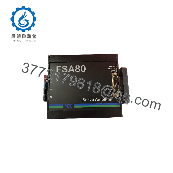
FSA80
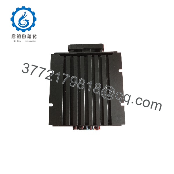
FSA80
Installation & Configuration Guide
Stage 1: Pre-Installation (Prep & Safety)
- Execute full Lock-Out/Tag-Out (LOTO) procedures on main battery disconnect switches and power distribution buses.
- Wear an ESD-grounded wrist strap to protect internal microcontrollers and logic ICs during wiring setup.
- Check battery supply terminals for correct polarity and verify bus voltage stays within the 24 to 80 V DC window.
- Record DIP switch settings, node addresses, and potentiometers (if applicable) on the existing amplifier card.
Stage 2: Removal
- Disconnect the main DC power connectors (+, -) and motor phase leads (M_1, M_2) using insulated tools.
- Unplug the multipin signal/feedback D-Sub connector from the front panel without pulling directly on the wire harness.
- Remove the panel mounting screws holding the amplifier heat sink baseplate to the enclosure wall.
- Lift the amplifier out carefully, avoiding impact to the external cooling fan housing.
Stage 3: Installation (Clone & Seat)
- Verify that the replacement drive model number is
FSA80to confirm matching voltage range and current capabilities. - Mount the replacement amplifier firmly onto a clean, unpainted metal backplate to ensure optimal thermal conductivity.
- Connect the signal D-Sub harness, ensuring retention jack-screws are fully tightened.
- Reconnect motor output wires (M_1, M_2) and main DC power leads (+, -), paying strict attention to polarity to prevent internal reverse-voltage damage.
Stage 4: Power-On & Testing
- Apply 24 V DC logic control power and verify that the front-panel POWER LED illuminates green while FAILURE remains off.
- Measure the main DC bus voltage across the drive terminals before enabling power stage output.
- Apply a low-amplitude analog velocity command (or CAN enable bit) to verify smooth motor rotation without current oscillations.
- Perform full-load acceleration and deceleration tests while monitoring the unit for abnormal thermal rise or overcurrent trip flags.
Firmware/Software Versions & Upgrade Notes
- System Controller Integration: The FSA80 interfaces directly with NDC CVC/CVP series AGV controllers or standard PLC motion modules via CANopen or \pm 10 V analog commands. Ensure the host controller parameter set matches the amplifier’s current scaling factor (15 A continuous / 30 A peak).
- Feedback Alignment: If paired with brushless DC motors, verify that motor commutation sensor phase angles (Hall effect or resolver offsets) match the drive feedback configuration. Incorrect commutation alignment will result in high current draw, uncontrolled motor runaway, or immediate overcurrent faults.
- Parameter Backups: Save drive configuration files or document analog tuning potentiometer turns prior to replacing active field units to streamline commissioning.
Frequently Asked Questions (FAQ)
Q: How can I be certain this FSA80 amplifier is genuine New Surplus and not refurbished?
A: This product is a Brand New Surplus unit. It is not used, not pulled from a decommissioned plant, and not refurbished. All modules undergo rigorous quality verification to ensure OEM-level reliability. Every unit features spotless power connector blocks, unmarred mounting holes, original fan assemblies without dust accumulation, and complete QC test reports.
Q: Why is New Surplus priced higher than refurbished servo drives found online?
A: Our pricing reflects the cost of securing genuine New Surplus inventory globally. It may be 20-30% higher than a refurbished gamble, but it is substantially less than OEM list prices, and it buys you 100% peace of mind. Refurbished power amplifiers often contain aged switching transistors and degraded capacitors, which are prone to sudden breakdown under peak current loads.
Q: Can the operate directly off a 24V or 48V battery system without additional voltage regulation?
A: Yes. The is designed specifically for wide DC input operation (24 to 80 V DC) and handles typical battery voltage swings, including charging float voltages and low-battery discharge curves within its operating envelope.
Q: What does a solid yellow or red LED indicate on the front panel?
A: A solid yellow LED usually indicates that the drive is DISABLED via software or physical hardware enable inputs. A solid red FAILURE LED indicates a fault condition such as short circuit, main bus overvoltage, undervoltage, or heat sink thermal overload.
Q: What warranty coverage applies to this New Surplus drive?
A: All New Surplus units are backed by a comprehensive 1-Year functional warranty. This guarantees that the meets original Danaher Motion factory performance standards for voltage control, current delivery, and thermal stability.



