
 WhatsApp: +86 16626708626
 Email:
  Phone: +86 16626708626
Description
3. Key Technical Specifications
| Parameter | Value |
|---|---|
| Manufacturer | Danaher Motion / Kollmorgen |
| Model Number | S21260-SRS |
| Product Type | Digital Brushless Servo Drive |
| Series | S200 |
| Input Voltage | 120 VAC or 240 VAC |
| Input Phase | Single-Phase or Three-Phase |
| Continuous Output Current | 12 ARMS |
| Peak Output Current | 18 ARMS |
| Peak Output Power | Up to 10,000 VA |
| Velocity Loop Bandwidth | Up to 800 Hz |
| Feedback Resolution | 24-bit High-Resolution Feedback |
| Communication Interface | SynqNet |
| Network Connector | RJ45 |
| Feedback Support | Smart Feedback Device (SFD) |
| Serial Communication | RS-232 Configuration Port |
| Protection Class | IP20 |
| Cooling Method | Convection / Cabinet Ventilation |
| Operating Temperature | 40 °C Rated at Full Current |
| Reduced Current Rating | 8 ARMS at 50 °C |
| Mounting Style | Panel Mount |
| Status | Discontinued OEM Product |
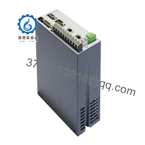
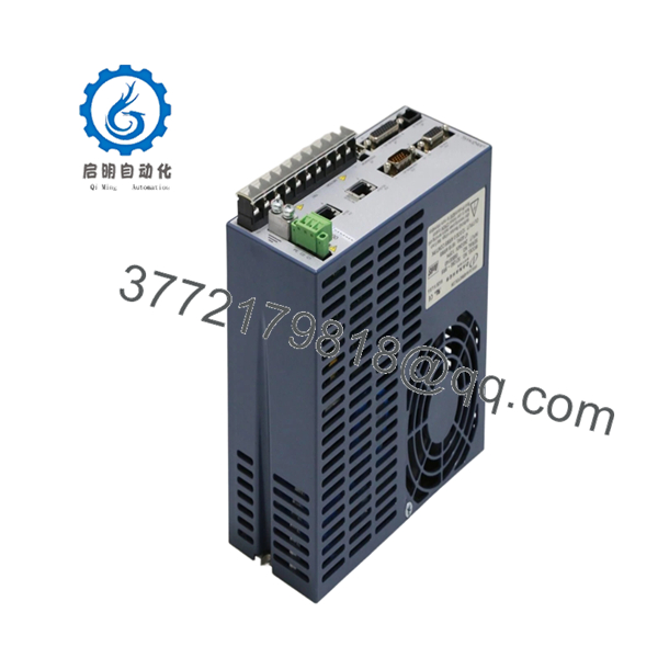
The Danaher Motion S21260-SRS is a digital servo amplifier from the Kollmorgen S200 family. It supports high-speed position, velocity, and torque control applications in semiconductor equipment, packaging systems, electronics assembly machinery, and precision automation platforms. The SRS suffix identifies the integrated SynqNet communication version used in coordinated motion-control architectures.
4. Product Introduction
The DANAHER S21260-SRS is a fully digital brushless servo drive used for high-performance motion control systems requiring precise positioning, velocity regulation, and torque control. It belongs to the Kollmorgen S200 platform and is commonly found in semiconductor manufacturing equipment, automated assembly systems, and packaging machinery.
Engineers typically select the S21260-SRS because of its fast servo response, integrated SynqNet networking, and 24-bit feedback capability. In real-world retrofit projects, maintaining encoder compatibility and preserving servo parameter backups are usually far more important than the hardware replacement itself.

- S21260-SRS
- S21260-SRS
5. Installation & Configuration Guide
Stage 1: Pre-Installation Preparation (10 Minutes)
⚠️ Safety First
- Notify operations and maintenance personnel.
- Place the machine in a safe maintenance condition.
- Lock out and tag out incoming AC power.
- Verify DC bus discharge before touching terminals.
- Wait at least 5 minutes after power removal.
Servo drives can retain dangerous DC bus voltage after shutdown.
Tools Required
- Grounded ESD wrist strap
- Fluke 115 multimeter
- PH1 screwdriver
- Torque screwdriver
- Wire labels
- Laptop with S200 Tools software
- Smartphone camera
- ESD work mat
Data Backup
- Upload and save all servo parameters.
- Record:
- Motor model
- Encoder type
- Node address
- SynqNet configuration
- Current tuning parameters
- Photograph:
- Power wiring
- Encoder wiring
- Communication ports
- Grounding points
❗ Always save the parameter file first. I’ve watched engineers spend an entire shift retuning a machine because nobody backed up the original drive settings.
Stage 2: Removing the Old Module (10 Minutes)
- Open the control cabinet.
- Label all motor and feedback cables.
- Disconnect:
- AC input power
- Motor outputs
- Encoder feedback
- SynqNet network cable
- Remove mounting hardware.
- Pull the drive straight out.
⚠️ Do not pull encoder connectors by the cable itself.
Connector damage is common during rushed shutdown work.
- Inspect:
- Terminal condition
- Cooling airflow path
- Ground connections
- Connector pins
⚠️ Important
Keep the original drive available until full motion verification is complete.
Stage 3: Installing the New Module (10 Minutes)
1. ESD Preparation
- Wear grounded wrist strap.
- Verify exact model number:
S21260-SRS
Do not assume S20360-SRS, S20660-SRS, and S21260-SRS are interchangeable simply because the connectors match.
2. Configuration Clone (Critical)
Restore:
- Servo tuning parameters
- Encoder settings
- Motor configuration
- SynqNet node settings
- Position scaling values
❗ This is the most common startup mistake. Factory-default parameters almost never match the machine. Clone the original setup whenever possible.
3. Mount the Drive
- Secure the drive to the mounting plate.
- Verify ventilation clearance.
- Confirm cabinet airflow direction.
4. Reconnect Wiring
- Connect AC input.
- Connect motor power.
- Connect encoder feedback.
- Connect SynqNet network cable.
- Verify protective earth grounding.
Self-Checklist
- Correct model verified
- Parameter backup restored
- Encoder connected
- SynqNet connected
- Ground bonded
- Cooling clearance verified
Stage 4: Power-On & Testing (15–20 Minutes)
Pre-Power Check
- Verify phase-to-ground resistance.
- Confirm grounding continuity.
- Inspect encoder cable integrity.
Power-Up Procedure
- Energize control power.
- Observe drive status indicators.
- Connect using S200 Tools software.
- Verify:
- Drive recognition
- Encoder detection
- Network communication
- Alarm history
- Restore parameter files if required.
- Perform low-speed jog testing.
- Verify homing operation.
- Confirm position accuracy.
⚠️ Troubleshooting Note
- Drive Fault Immediately After Startup: Verify motor and encoder configuration.
- No SynqNet Communication: Check node addressing and RJ45 connections.
- Position Error Fault: Verify encoder scaling and motor feedback setup.
- Oscillation During Motion: Review velocity loop tuning.
Common Field Pitfalls Engineers Encounter
❗ Firmware and Parameter Mismatch
Most replacement failures are not hardware failures.
They’re configuration failures.
I worked a semiconductor handler retrofit where the replacement drive powered up perfectly but continuously generated following-error alarms. The root cause was a missing parameter restore.
Avoidance: Export the entire parameter set before removal and restore it after installation.
❗ Encoder Configuration Problems
Servo systems live and die by feedback quality.
A single encoder mismatch can prevent referencing, homing, or stable positioning.
Several experienced motion-control technicians point out that encoder alignment and offset configuration often require drive-level setup rather than simple mechanical alignment.
Avoidance: Document encoder type, resolution, and offset values before replacement.
❗ SynqNet Network Configuration Errors
The SRS version uses SynqNet communications.
Incorrect node configuration can make a healthy drive appear completely offline.
Avoidance: Record node assignments and network topology before shutdown.
❗ Power Supply Capacity Assumptions
Engineers often focus on motor current and forget cabinet loading.
The S21260-SRS can deliver:
- 12 ARMS continuous
- 18 ARMS peak
Startup current demand can expose weak power systems.
Avoidance: Maintain at least 20% spare supply capacity.
❗ Electrostatic Discharge (ESD)
Servo drives are particularly vulnerable during installation.
I once watched a contractor unpack a replacement drive directly onto a painted electrical cabinet during winter. The drive booted, but encoder communication faults appeared within minutes.
That replacement ended up back on the bench.
Avoidance: Ground strap, ESD mat, anti-static handling every time.
Keep these checks in mind and you’ll save yourself 90% of typical rework time.
6. Frequently Asked Questions (FAQ)
Q1. Is the S21260-SRS a servo drive or a motion controller?
It is primarily a digital brushless servo drive.
The drive performs motor control functions while communicating with a higher-level motion controller through SynqNet networking.
Q2. Can I hot-swap the S21260-SRS?
No.
Removing the drive under power can damage the DC bus, encoder electronics, or communication network.
Always remove power first.
Q3. Is the S21260-SRS obsolete?
Yes.
The S200 family has been discontinued for many years.
Most available inventory today comes from:
- New Surplus stock
- Machine decommissioning programs
- Refurbished inventory
- Strategic spare-parts holdings
Q4. What does the SRS suffix mean?
The SRS designation identifies versions equipped with SynqNet communication hardware.
These drives use networked motion-control architecture rather than standalone analog-only control methods.
Q5. Will I lose machine positioning if I replace the drive?
Possibly.
Many positioning parameters, scaling values, and encoder settings reside inside the drive configuration.
Always perform a complete parameter backup before replacement.
Q6. What testing should be completed before shipment?
A proper supplier should perform:
- OEM label verification
- Visual inspection
- Power-on diagnostics
- Encoder interface verification
- SynqNet communication testing
- Alarm log inspection
- 24-hour load testing
- 500 V insulation resistance test (>10 MΩ)
- Firmware documentation
- Final QC sign-off
Test reports and startup videos should be available upon request.
Q7. What is the most common installation mistake?
Losing the original servo parameters.
Honestly, hardware replacement is usually the easy part.
The real problem starts when somebody installs the new drive and realizes:
- Encoder scaling was never documented
- Homing offsets were never saved
- Servo tuning files are missing
At that point, the machine may power up perfectly but still refuse to run production.
That scenario is far more common than actual drive failure.


