
 WhatsApp: +86 16626708626
 Email:
  Phone: +86 16626708626
Description
Key Technical Specifications
| Parameter | Value |
|---|---|
| Manufacturer | DEIF A/S |
| Model | AGC 242 |
| Product Family | AGC-200 / Multi-line |
| Product Type | Advanced genset controller and power-management controller |
| Primary Application | Parallel generator control, load sharing, synchronizing, islanded power plants, and critical standby systems |
| AGC 242 Variant Number | 23 |
| Generator Capacity | Up to 32 generators in specified island power-management arrangements |
| CANshare Capacity | Up to 128 generators for multi-genset load sharing |
| Bus Tie Breaker Capacity | Up to 8 bus tie breakers |
| Mains Feeder Capacity | Up to 32 mains feeders in applicable multi-controller plant configurations |
| Generator Voltage Measurement | 100–690 V AC, phase-to-phase, +20% |
| UL/cUL Voltage Limit | 100–600 V AC |
| Measuring Frequency | 30–70 Hz |
| Generator Current Measurement | 1 A or 5 A AC current-transformer secondary |
| CT Burden | 0.3 VA per phase maximum |
| Auxiliary Supply | 6–36 V DC continuous |
| UL/cUL Auxiliary Supply | 9–32.5 V DC |
| Supply Protection | 12 A slow-blow fuse required |
| Maximum Power Consumption | 25 W standard; 45 W with low-temperature display option |
| Operating Temperature | −25 to +70 °C |
| Low-Temperature Option | −40 to +70 °C with L2 display-heater option |
| Storage Temperature | −40 to +70 °C |
| Maximum Humidity | 97% RH to IEC 60068-2-30 |
| Operating Altitude | Up to 4,000 m above sea level |
| Digital Inputs | 14 configurable inputs |
| Multifunction Inputs | 3 configurable inputs |
| Emergency Stop Input | 1 |
| Configurable Relay Outputs | 14 |
| CAN Interfaces | Three: CAN A, CAN B, and CAN C |
| RS-485 Interface | One Modbus RTU slave interface |
| Ethernet | TCP/IP Modbus option available |
| USB Port | USB 2.0 Type B service port |
| Data Logging | Event, alarm, battery-test, and engine-diagnostic logs with real-time clock |
| Memory Card | SD card supported |
| Display | 240 × 128-pixel backlit STN display |
| Panel Size | 312 × 219 mm |
| Panel Cutout | 297 × 204 mm |
| Unit Depth | 87 mm |
| Approximate Weight | 1.6 kg / 3.5 lb |
| Front Protection Rating | IP52 / NEMA Type 1 standard |
| Optional Front Protection | IP66 with L1 display gasket |
| Terminal Protection Rating | IP20 / NEMA Type 1 |
| Safety Standard | EN 61010-1, UL 508, CSA C22.2 No. 14-05 |
| Communications / Setup Tool | DEIF Multi-line 2 PC Utility Software |
| Lifecycle Note | Verify exact order number, options, software revision, and saved application before replacement |
DEIF identifies the AGC 242 as Variant 23 of the AGC-200 controller range. It supports island power management, multi-generator load sharing, up to 32 generators and eight bus tie breakers in specified systems, while CANshare configurations can support up to 128 generators.
Product Introduction
The DEIF AGC242 is an Advanced Genset Controller for generator synchronization, load sharing, breaker control, protection, and power management. It is used in parallel diesel or gas generator plants, islanded power systems, emergency standby installations, peak-shaving plants, fixed-power systems, and grid-parallel applications. The controller measures three-phase generator and busbar values, controls generator breakers, and coordinates multiple gensets through CANshare and power-management logic.
The AGC242 is the correct choice when a plant needs more than basic automatic mains failure control. It provides multi-genset island operation, load-dependent start/stop, load management, spinning reserve logic, fuel-optimization priority selection, bus-tie control, event logging, and configurable M-Logic. Verify the full order code and enabled software options because Ethernet, Modbus functions, protection packages, low-temperature display heating, and application functions may vary by unit.
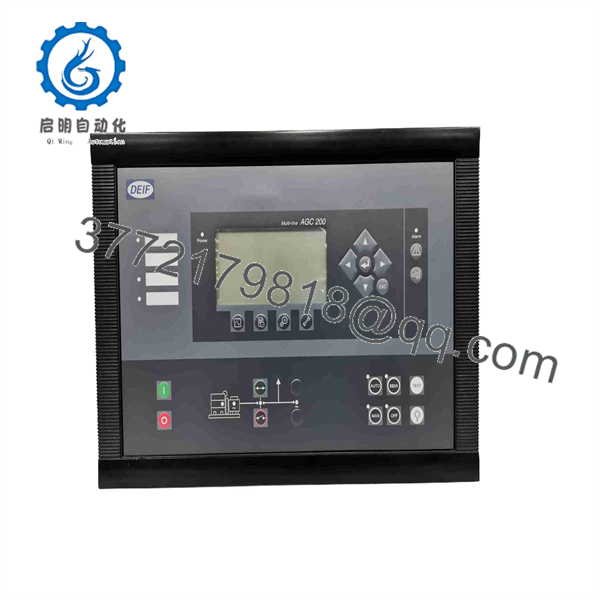
AGC242
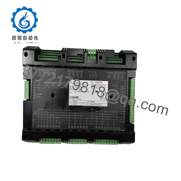
AGC242
Troubleshooting Quick Reference
| Symptom | Possible Cause | Relevance to this Part | Quick Check Method | Recommendation |
|---|---|---|---|---|
| Controller display is completely blank | Missing DC supply, blown 12 A fuse, loose battery connection, reversed polarity, failed controller | ⚠️ Medium | Measure 6–36 V DC at the controller supply terminals; check the required 12 A slow-blow fuse, battery isolator, and negative return | Verify stable DC supply before replacing the AGC242. The controller can ride through a 0 V cranking drop for 50 ms only under stated conditions |
| Unit restarts during engine cranking | Weak battery, voltage drop in control wiring, undersized supply conductors, poor negative return | ❌ Low | Record DC voltage at the AGC supply terminals during cranking; inspect battery condition, cable lugs, fuse holders, and common return path | Repair the battery or supply circuit first. A healthy replacement controller will reset under the same voltage collapse |
| Generator starts but breaker will not close | Synchronization criteria not met, generator voltage/frequency out of range, breaker feedback missing, interlock active | ⚠️ Medium | Check generator and bus voltage, phase sequence, frequency, synchronization screen, breaker close coil, and GB auxiliary contacts | Use the event log before changing settings. Do not bypass synchronism check or breaker interlocks |
| “GB Close Failure” alarm | Failed breaker close coil, blown close-circuit fuse, missing breaker-position feedback, mechanical breaker issue | ❌ Low | Command a close during an approved test; measure voltage at the breaker close coil and verify the GB ON auxiliary contact returns | Check breaker mechanics and the close circuit before replacing the AGC242 |
| Generator breaker closes, then trips immediately | Reverse power, overcurrent, voltage/frequency protection, incorrect CT polarity, wrong protection settings | ⚠️ Medium | Read the exact ANSI alarm and event timestamp; compare CT polarity and phase assignment to the single-line diagram | Do not simply reset the alarm. Correct CT orientation, wiring, or settings before reconnecting a generator |
| Reverse-power alarm after synchronization | CT polarity reversed, incorrect kW sign, governor not accepting load, wrong phase assignment | ❌ Low | Compare real-power direction on the display with clamp-meter readings; verify CT S1/S2 orientation and generator phase mapping | Correct CT wiring or configuration. This is one of the most common commissioning errors in parallel-generator plants |
| Load sharing is unstable between generators | CANshare wiring issue, wrong droop/isochronous settings, governor or AVR mismatch, inconsistent CT scaling | ⚠️ Medium | Check CAN A/B/C termination and controller IDs; compare kW/kvar values, governor response, and active load-share mode | Troubleshoot communications and engine/AVR tuning before replacing the controller |
| One AGC242 is offline in a parallel plant | CAN network open circuit, duplicate node ID, failed CAN termination, missing power supply | ⚠️ Medium | Measure CAN_H/CAN_L continuity, inspect terminating resistors, check node addresses, and review CAN diagnostics | Restore the network segment first. A single bad termination can affect multiple controller nodes |
| Modbus SCADA values are missing | Wrong RS-485 polarity, incorrect baud rate/parity/address, Modbus option/configuration issue | ❌ Low | Check RS-485 A/B wiring, shielding, ground reference, slave address, baud rate, parity, and SCADA polling table | Verify Modbus settings before replacing the AGC242. The controller supports RS-485 Modbus RTU slave communication |
| Ethernet connection does not work | Ethernet option not installed or enabled, IP conflict, incorrect network settings, damaged cable | ⚠️ Medium | Verify the unit’s order configuration and enabled option; check RJ45 link LED, IP address, subnet, gateway, and switch port | Do not assume Ethernet is standard. TCP/IP Modbus requires the relevant DEIF option |
| Engine alarms are not displayed through J1939 | Wrong CAN engine interface, ECU protocol mismatch, damaged CAN wiring, incorrect engine configuration | ⚠️ Medium | Confirm engine ECU protocol, CAN C wiring, termination, and communication status; compare engine ECU address/settings | Verify engine interface compatibility before changing the controller or engine ECU |
| Mains failure sequence does not start | AMF mode disabled, incorrect mains measurement wiring, undervoltage delay set too long, start permissive missing | ⚠️ Medium | Measure mains voltage at controller inputs; check active plant mode, AMF settings, start inhibit, and event log | Confirm the configured operating mode. functions depend on the approved application setup |
| Controller trips on false voltage alarms | Loose measuring wire, incorrect voltage selection, blown sensing fuse, phase sequence issue, poor terminal torque | ❌ Low | Compare controller readings with a calibrated meter at the voltage input terminals; inspect fuses and terminal screws | Repair sensing wiring first. Do not apply 690 V AC unless the installed configuration and wiring are rated for it |
| Replacement controller powers up but does not run the plant | Missing application configuration, incorrect variant/options, incompatible software version, unsaved settings | ✅ High | Compare order number, variant, software revision, option list, I/O map, CAN IDs, and saved setup file with the removed unit | Restore the verified application through DEIF PC Utility Software before placing the controller in Auto |
| No event history after replacement | New controller has no copied configuration/log data | ❌ Low | Check whether the old unit’s setup and log files were exported before removal | Preserve the original controller data before replacement. Event history is often the fastest path to finding a recurring plant fault |
| Display is unreadable in cold weather | Ambient temperature below standard range, display heater option absent, condensation or panel damage | ⚠️ Medium | Check ambient temperature and installed options; inspect display and enclosure sealing | Use the L2 low-temperature display option for installations down to −40 °C |
❗ Synchronization warning: Never force the generator breaker closed to “see if it will hold.” Verify voltage magnitude, frequency, phase rotation, phase angle, breaker feedback, and synchronism settings first. Closing out of phase can damage couplings, breakers, generator windings, and driven equipment.
❗ CT-polarity warning: A reversed current transformer secondary can produce reverse-power alarms, unstable load sharing, or a generator that refuses to accept load. Photograph CT labels, S1/S2 terminals, and phase assignments before changing anything.
❗ Configuration warning: The stores plant-specific settings for generator protection, breaker logic, delays, load sharing, CAN communication, M-Logic, and operating modes. Do not install a spare without a verified configuration backup and a controlled commissioning plan.
❗ Battery-supply warning: The auxiliary supply requires a 12 A slow-blow fuse. A controller reboot during crank is usually a battery/cable/grounding problem, not a failed . Measure voltage at the actual controller terminals, not only at the battery.
If the fault remains unresolved, send technical support photos of the full order label, rear terminals, DC supply fuse, generator and mains sensing circuits, CT connections, breaker coils and auxiliary contacts, CAN wiring, active alarms, event log, software version, and saved configuration file.
Frequently Asked Questions
What does the DEIF do?
The controls and protects generator sets in standalone and parallel power plants. It performs generator synchronization, breaker control, active and reactive load sharing, generator and busbar measurement, protection, event logging, and power-management functions. It can operate in island mode, automatic mains failure, fixed power, peak shaving, load takeover, and mains power-export applications.
How many generators can the manage?
For documented island power-management configurations, it can manage up to 32 generators and up to eight bus tie breakers. In multi-genset load-sharing applications using CANshare, DEIF specifies support for up to 128 generators. The final capacity depends on the selected plant architecture, companion AGC variants, CAN configuration, and approved application design.
What are the voltage and current inputs?
The controller measures 100–690 V AC phase-to-phase at 30–70 Hz and accepts 1 A or 5 A AC CT secondary inputs with a maximum burden of 0.3 VA per phase. For UL/cUL applications, the voltage rating is limited to 600 V AC and listed or recognized current transformers are required.
Can communicate with a SCADA system?
Yes. The standard controller includes one RS-485 Modbus RTU slave interface and three CAN interfaces. TCP/IP Modbus is available as an option. Confirm the installed option list, firmware version, network settings, port assignment, and SCADA register map before procurement.
Does the support automatic mains failure?
Yes. The supports AMF operation, including use in multi-generator power-management systems. It can also support fixed-power operation, peak shaving, load takeover, mains power export, and island operation based on the configured plant design.
Can I hot-swap an ?
No. Do not remove or install an while it controls an energized generator or breaker system unless an approved plant-specific maintenance procedure explicitly permits the work. Transferring control, disabling Auto mode, isolating control circuits, recording all active alarms and forces, and verifying breaker state are mandatory steps in a safe replacement plan.
Will my settings remain when I replace the ?
Not automatically. The replacement controller must receive the approved configuration file, including generator ratings, CT/PT scaling, protection thresholds, breaker logic, engine ECU settings, load-share configuration, CAN IDs, Modbus settings, I/O assignments, and M-Logic. Export the original configuration using DEIF Multi-line 2 PC Utility Software before hardware removal whenever possible.
Why does the controller show a reverse-power alarm after replacement?
The usual causes are reversed CT polarity, an incorrect current phase mapping, wrong kW sign convention, or a governor that is not accepting load. Verify current-transformer S1/S2 polarity, corresponding voltage phases, generator rotation, and active-power readings before adjusting protection settings. Do not disable 32R protection to get a unit online.
Why is a new-surplus cheaper than a current factory unit?
New-surplus equipment may originate from spare inventory, canceled projects, panel-builder overstock, or an upgraded plant. It can cost less because it is not supplied through the current OEM distribution path. Request full order-code photos, software revision, option list, serial number, packaging condition, test evidence, warranty, return terms, and confirmed lead time before purchasing.
What condition should I request for a production-critical spare?
Request New Original / New Surplus with clear photos of the DEIF identification label, complete order number, option list, rear terminals, and original packaging. For Refurbished (tested) equipment, require documented tests of DC supply performance, generator/mains voltage inputs, CT inputs, digital I/O, relay outputs, CAN, RS-485, USB service connection, display/keypad operation, and sustained runtime. For a parallel plant, also request a controlled synchronization and load-sharing simulation report before accepting the unit.



