WhatsApp: +86 16626708626
 Email:
 Phone: +86 16626708626
Description
3. Key Technical Specifications
| Parameter | Value |
|---|---|
| Measuring current (In) | 0.3–5.0 A AC (selectable modules) |
| Measuring voltage (Un) | 57.7–690 V AC |
| Frequency range | 40…45…65…70 Hz |
| Supply voltage | AC: 57.7–690 V ±20 % (max. 3.5 VA) / DC: 24–220 V −25/+30 % (max. 2.5 W) |
| Contact outputs (speed control) | 2 make contacts, 250 V AC / 24 V DC, 8 A |
| Analogue outputs (PS/FS lines) | −5 to 0 to +5 V |
| Operating temperature | −25 °C to +70 °C |
| Mounting | 35 mm DIN rail or base (screw) |
| Weight | Approx. 0.75 kg |
| Protection | Case IP40, terminals IP20 |
| Dimensions | 150 × 75 × 110 mm |
4. Product Introduction
The DEIF LSU-112DG is a Uni-line load-sharing unit that controls the prime mover of diesel or gas generators. It performs frequency control in stand-alone mode and combined frequency-plus-power control when paralleled with other units or the grid.
It includes built-in power (I × cos φ) and frequency transducers, constant-power or isochronous modes, and dual relay outputs for speed regulation. The unit mounts on 35 mm DIN rail or by base screws and interfaces directly to mechanical governors or, via DEIF electronic potentiometers (EPN-110DN / EPQ-96), to electronic governors. Verify exact voltage/current module configuration and governor compatibility against the OEM datasheet before installation.
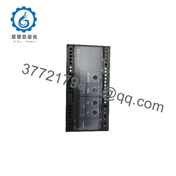
LSU-112DG
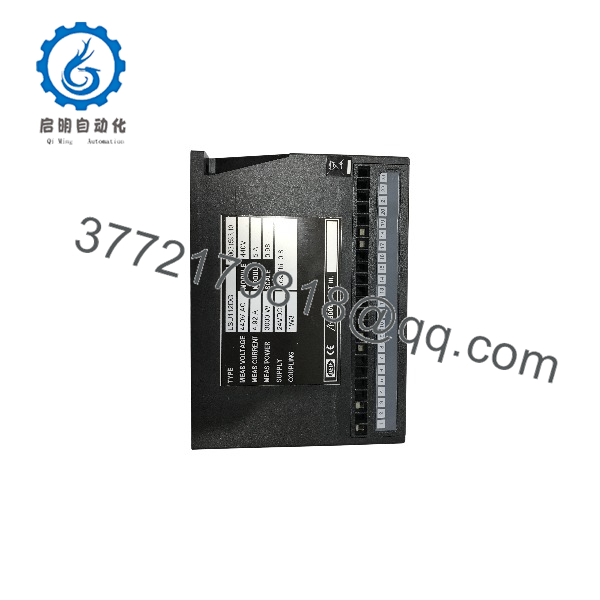
LSU-112DG
5. Troubleshooting Quick Reference
| Symptom | Possible Cause | Relevance to this Part | Quick Check Method | Recommendation |
|---|---|---|---|---|
| No green POWER LED or flashing 2–3 Hz | Supply voltage missing or microcontroller fault | ✅ High | Measure auxiliary supply at terminals 1/3; observe LED | Confirm supply within rated range; replace unit if flashing persists |
| No speed-increase/decrease pulses | Deadband too wide or Xp/Tn settings incorrect | ✅ High | Check front potentiometers (Xp, Tn, Tp) and deadband jumpers | Adjust proportional band and min. ON time; verify wiring to governor |
| Uneven load sharing between units | PS/FS paralleling lines open or polarity reversed | ✅ High | Measure voltage on PS (40/41) and FS (38) lines between units | Verify continuous paralleling bus and correct polarity |
| Unit stays at zero power | Unload input (33/34) permanently closed | ❌ Low | Check status of unload contact | Open unload contact or remove short |
| Incorrect power reading | Current transformer polarity or ratio mismatch | ✅ Medium | Confirm S1/S2 wiring to terminals 28/29 and CT ratio vs. calibrated In | Reverse CT leads if necessary; match module to actual CT secondary |
If the fault remains after these checks, photograph the front settings, terminal wiring, and LED states, then contact technical support with the diagnostic details.
6. Frequently Asked Questions (FAQ)
Q: Is the LSU-112DG new original or refurbished?
A: This unit is New Original (New Surplus). It has never been installed in a running plant. We perform visual inspection, power-on self-test, and basic functional verification of the transducers and relay outputs before packaging.
Q: Can I use the LSU-112DG with an electronic speed governor?
A: Yes, but only when paired with a DEIF electronic potentiometer (EPN-110DN or EPQ-96). The unit itself is designed for mechanical governors; the potentiometer converts the relay pulses into the analogue signal required by most electronic governors.
Q: What voltage and current modules are available?
A: Measuring voltage modules cover 57.7–690 V AC. Measuring current modules are selectable from 0.3 A to 5.0 A AC. Confirm the exact modules fitted on the unit label before ordering so they match your PT/CT ratios.
Q: Does the unit support unbalanced loads?
A: The built-in I × cos φ transducer assumes balanced load (1W3 or 1W coupling). For unbalanced systems, connect an external 4–20 mA power transducer to terminals 31/32; the internal transducer is then automatically disabled.
Q: How do I set constant-power (isochronous) versus droop mode?
A: Constant-power mode is selected by wiring the reference input (terminal 35) and using the front DERATING potentiometer. Isochronous or droop behaviour is determined by the paralleling-line connections and the Xp setting. Refer to the installation instructions for the exact jumper and potentiometer combination required.
Q: What is the typical lead time and warranty?
A: Stock units ship within a few business days after payment. Warranty is 1 year against manufacturing defects under normal operating conditions.