
 WhatsApp: +86 16626708626
 Email:
  Phone: +86 16626708626
Description
| Parameter | Specification |
| Measuring Voltage (U_N) | 57 to 690 V AC (depends on ordering variant) |
| Measuring Current (I_N) | 1 A or 5 A AC from CTs |
| Supply Voltage | 57 to 690 V AC (derived from measuring lines) or 12/24 V DC auxiliary |
| Operating Frequency | 40 to 70 Hz |
| Control Outputs | Relay outputs (increase/decrease speed governor pulses) or analog (±5 V DC, 0-10 V DC, 4-20 mA) |
| DC Bus Line Signal | 0 to 5 V DC analog load sharing bus (DC lines connected across generators) |
| Power Consumption | Max 4.5 VA per phase voltage circuit |
| Relay Contact Rating | 250 V AC, 2 A / 24 V DC, 2 A (resistive) |
| Operating Temperature | -25°C to +70°C (-13°F to +158°F) |
| Mounting Type | 35 mm DIN rail or baseplate mount |
| Enclosure Protection | IP40 front panel, IP20 rear housing |
| Compliance & Approvals | CE, DNV-GL, ABS, LR, BV (Marine classification rated) |
The DEIF LSU-113DG is a precision load sharing controller designed to automatically share active power (kW) proportionally between two or more diesel generators operating in parallel, or between a generator and a utility grid. It interfaces directly with speed governors or electronic fuel control systems via pulse or analog control signals to balance generator engine output without requiring complex PLC networks.
The module incorporates built-in reverse power protection, frequency control, and dead-band adjustments to prevent engine hunting under shifting electrical loads. Utilizing a simple 2-wire DC load-sharing bus between units, the LSU-113DG maintains system stability in critical marine propulsion, offshore power rigs, and industrial standby power applications.
Quality Control & SOP Transparency
Every DEIF LSU-113DG in our warehouse passes a strict 5-stage verification process prior to dispatch to eliminate site commissioning failures:
- Inbound Inspection & Traceability:
- Source verification against original DEIF factory certificates.
- Holographic label audit and physical housing inspection (no cracked DIN tab clips or UV damage).
- Live Functional Testing:
- Tested on a dedicated 3-phase generator simulator rack using Fluke 115 multimeters and calibrated signal injection units.
- Verified power-on LED self-test, dead-band adjustment potentiometers, and internal relay click transitions.
- Simulating 0-100% current/voltage unbalanced loads to confirm accurate DC bus line signal output (0-5 V DC).
- 24-hour continuous burn-in load test under thermal monitoring.
- Electrical Parameter Testing:
- Insulation resistance test via 500 V Megger (>10 MΩ between power/measurement terminals and chassis ground).
- Configuration Check:
- Verification of factory DIP switch settings and potentiometer reference points documented via high-resolution photos.
- Final ESD Packaging:
- Sealed in anti-static ESD shielding, wrapped in heavy bubble cushioning, and labeled with dated QC sign-off tags.
- Full test videos and calibration datasheets available upon request.
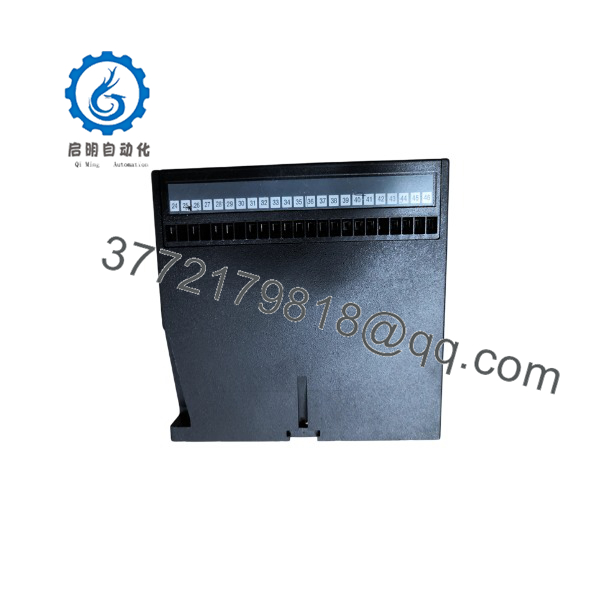
LSU-113DG
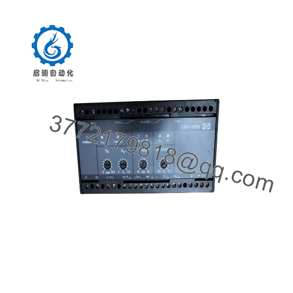
LSU-113DG
Technical Pitfall & Survival Guide
⚠️ 1. Current Transformer (CT) Phase Alignment Mismatch
- Issue: Connecting the CT to the wrong phase or reversing S1/S2 polarity causes the module to read negative power or calculate wildly inaccurate load percentages, tripping reverse power alarms.
- Avoidance: Verify that Phase L1 CT matches L1 voltage measurement. Ensure S1 (K) goes to terminal 13 and S2 (L) goes to terminal 14 (verify exact terminal map on side sticker).
- Anecdote: I’ve seen marine engineers spend 12 hours troubleshooting engine hunting, only to find the CT on Phase L1 was installed backwards after a generator overhaul.
⚠️ 2. DC Load-Sharing Bus Polarity and Loop Grounding
- Issue: Reverse polarity or double-grounding on the analog DC sharing bus (terminals connecting multiple LSU-113DG units together) breaks load balance across all sets.
- Avoidance: Parallel connection requires strict + to + and – to – bus wiring. Never ground the DC bus line at multiple points; leave it isolated or grounded at the master panel only.
⚠️ 3. Governor Interface Sensitivity (Dead-band Setting)
- Issue: Adjusting the impulse speed sensitivity potentiometer (T_N / X_P) too tight causes constant governor pulse hunting, prematurely wearing out actuator relays or unstable engine RPM.
- Avoidance: Start commissioning with wide dead-band settings. Gradually narrow the X_P gain dial until the generator responds within ±2% of system target without oscillating.
⚠️ 4. Auxiliary Supply Voltage Variations
- Issue: Applying 24 V DC to a unit variant configured exclusively for AC line-power measurement destroys internal step-down transformers.
- Avoidance: DEIF produces several LSU-113DG ordering options (e.g., self-powered vs. external DC auxiliary). Always check the exact side-label code before applying power.
Estimated Time: 25 to 35 minutes
Stage 1: Pre-Installation Preparation
- ⚠️ Safety First: Lock out and tag out (LOTO) generator main breakers and engine auto-start controls. Ensure the generator set is stationary and engine starting circuit is isolated. Verify zero voltage on measuring lines using a calibrated multimeter.
- Tools Required: Precision flathead screwdriver (2.5 mm), ESD wrist strap, multimeter, wire markers, smartphone.
- Data Backup: Photograph front dial positions (Dead-band X_P, Integration time T_N, Frequency setting) and terminal block wiring tags.
Stage 2: Removing the Old Module
- Unplug heavy-gauge terminal strips or unfasten screw terminals individually.
- Label wire pairs: U_M (voltage sensing), I_M (CT inputs), Speed Governor contacts, and DC Bus terminals.
- Release the bottom DIN-rail spring catch with a flathead screwdriver and lift the unit outward.
Stage 3: Installing the New Module
- Put on an ESD wrist strap. Match the exact DEIF product suffix on the side label (e.g., LSU-113DG 100-110V AC).
- Set front potentiometers (X_P, T_N) to match the settings recorded from the previous unit.
- Snap the module onto the 35 mm DIN rail.
- Wire terminals according to the scheme. Torque screw terminals to 0.5 Nm (4.4 in-lbs).
- Self-Checklist: [ ] Voltage sensing phase correct, [ ] CT polarity S1/S2 verified, [ ] DC Load Sharing bus polarity matched.
Stage 4: Power-On & Testing
- Energize control circuits and start the generator in manual mode (keep main breaker open).
- Measure incoming AC voltage at terminals to ensure it matches the nameplate rating.
- Observe front panel LED indicators: “Power” LED should illuminate solid green.
- Close the generator breaker onto a dummy load bank. Verify that the output relays/analog signals adjust engine speed to match load demand smoothly.
- ⚠️ Troubleshooting Note: If the generator sheds load rapidly upon closing the breaker, immediately swap the CT input leads (S1 and S2); the module is detecting false reverse power.
Q: Can I use the with an electronic speed governor that accepts an analog 0-10V or 4-20mA input instead of pulse relays?
A: Yes, depending on the specific model variation ordered. Standard units come with pulse relay output contacts (increase/decrease engine speed), while specific variants include analog outputs (\pm 5 V, 0–10 V, or 4–20 mA) designed to interface directly with electronic speed control modules like Heinzmann, Woodward, or Cummins EFCs. Verify your specific sub-part number before connecting analog lines.
Q: Is the DEIF compatible with older LSU-112 or LSU-114 models in the same system?
A: Yes, the uses the same standardized 0 to 5 V DC load-sharing bus architecture as other DEIF 100-series load sharing relays. As long as the parallel DC bus terminals are wired in parallel across all units, an can operate alongside older LSU-112DG or LSU-114DG modules on the same switchboard.
Q: What happens if the DC load sharing bus wires break while generators are running in parallel?
A: If the DC load sharing bus cable is cut or disconnected, the loses its reference signal from the other running gensets. The module will typically default to its baseline frequency setting rather than balancing load dynamically. While the generators won’t immediately trip on overload, active power (kW) will drift apart over time as plant load changes.
Q: Why is your price lower than the OEM factory direct list price?
A: We source new surplus inventory, excess shipyard project stock, and panel builder overstock directly. Every item undergoes physical inspection, functional bench testing, and insulation verification. You receive genuine OEM hardware backed by our standard 1-year replacement warranty without waiting for multi-week factory lead times.
Q: Does the handle reactive power (kVAR) and voltage control?
A: No. The is designed specifically for active power (kW) load sharing through the engine speed governor. For reactive power (kVAR) load sharing and automatic voltage regulator (AVR) control, you must pair it with a dedicated VAR sharing unit such as the DEIF Delomatic or DEIF RPF-112D relay.



