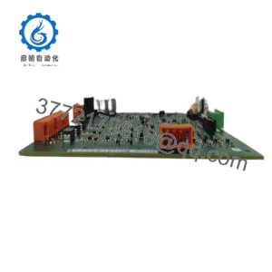
WhatsApp: +86 16626708626
 Email:
 Phone: +86 16626708626
Description
Core Product Summary
The DEIF PPU/2/GS (also referenced as PPU-2/GS or PPU2GS) is a microprocessor-based generator paralleling and protection unit from the Multi-line 2 product family. It integrates synchronization, load sharing, electrical protection, and three-phase measurement functions for generator-set applications.
The unit is designed for installation inside a switchboard and supports both stand-alone and parallel operation of generators. It continuously measures voltage, current, frequency and related parameters, presents values and alarms on an LCD display, and can operate with a remote door-mounted display. Auxiliary supply is typically 12/24 V DC. Measurement inputs cover 100–690 V AC voltage and 1 A or 5 A current transformer ranges.
Key Technical Specifications
| Parameter | Value |
|---|---|
| Product type | Generator paralleling and protection unit |
| Product family | Multi-line 2 |
| Model designation | PPU/2/GS (PPU-2/GS) |
| Measurement voltage | 100–690 V AC |
| Measurement current | -/1 A or -/5 A |
| Auxiliary supply | 12/24 V DC |
| Core functions | Automatic synchronization, active/reactive load sharing, generator protection |
| Display | LCD (values and alarms); optional remote door-mount display |
| Mounting | Inside switchboard (DIN rail or screw mounting) |
| Measuring principle | True 3-phase RMS |
| Operating temperature | –25 °C to +70 °C (typical documented range) |
Detailed Product Overview
The DEIF PPU/2/GS belongs to the Multi-line 2 range of multi-function generator control and protection products. It combines the essential functions required for safe paralleling and protection of a synchronous generator into a single compact unit. The controller performs automatic synchronization by matching voltage, frequency and phase angle before issuing a breaker close command. After paralleling it manages active-power and reactive-power load sharing among multiple generators or between a generator and the mains.
Protection functions include monitoring of over- and under-voltage, over- and under-frequency, reverse power and additional generator-related conditions. All measured values and alarm states are presented on the integrated LCD. The main unit is intended for mounting inside the switchboard; a separate display unit can be installed on the cabinet door and connected by cable when operator access from the front is required.
The design supports stand-alone (island) operation as well as parallel operation with other generators or with the utility grid. Configuration is performed via the front-panel interface or supporting tools, allowing selection of control modes such as fixed frequency, base-load, droop or isochronous load sharing. The unit contains the necessary three-phase measuring circuits for voltage and current, with galvanic isolation appropriate to the application voltage range.
Because the Multi-line 2 platform offers a modular option structure, the exact complement of additional protection, analogue outputs, serial communication or power-management features depends on the ordered hardware options. System integrators must therefore verify the complete type code and option list against the application requirements.
System Compatibility & Integration Requirements
| Item / Dependency | Verified Compatibility or Requirement | Practical Note |
|---|---|---|
| Product family | DEIF Multi-line 2 | Same platform as GPU and GPC variants |
| Mounting location | Inside switchboard | DIN-rail or rear-screw mounting; remote display option available |
| Voltage measurement | 100–690 V AC | True RMS, three-phase |
| Current measurement | 1 A or 5 A CT secondary | Selectable range |
| Auxiliary power | 12/24 V DC | Typical documented supply |
| Control modes | Stand-alone, parallel with other gen-sets, parallel with mains | Configurable via parameters |
| Display | Local LCD or remote door-mounted display | Connected by dedicated cable when remote |
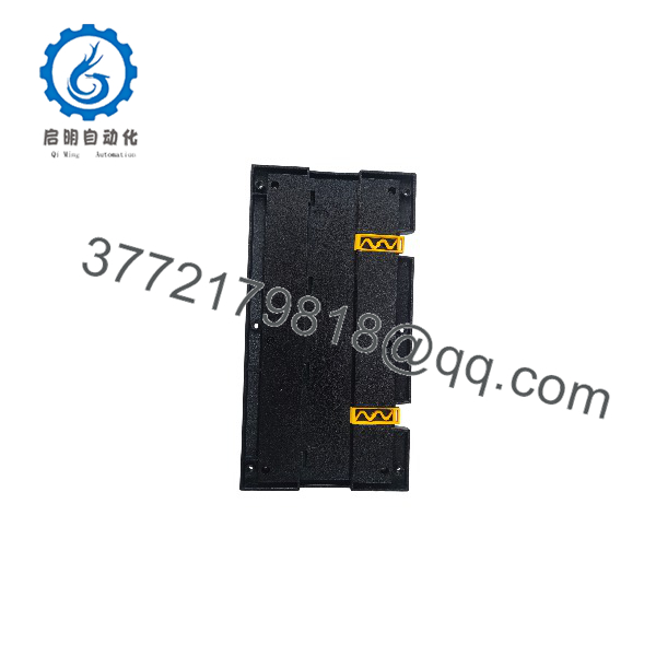
PPU/2/GS
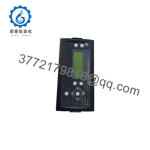
PPU/2/GS
Dimensions, Mounting & Connection Notes
The unit is designed for internal switchboard installation. It can be clipped onto a DIN rail or fastened with screws using the base mounting holes. When a remote display is used, the display is mounted on the switchboard door and linked to the main unit by a display cable. Panel cut-out and fixing dimensions are defined in the product documentation to ensure correct mechanical fit.
Measurement connections for voltage and current transformers, auxiliary supply, digital inputs, relay outputs and any optional communication interfaces are brought out to terminal strips. Proper shielding and separation of measurement, control and power wiring are required for reliable operation. The exact terminal layout depends on the selected hardware options.
FAQ
What is the DEIF PPU/2/GS?
It is a Multi-line 2 generator paralleling and protection unit that combines synchronization, load sharing and electrical protection functions for gen-set applications.
What does the GS designation indicate?
GS identifies the generator-synchronizing version of the PPU within the Multi-line 2 family.
Where is the unit mounted?
The main unit is mounted inside the switchboard (DIN rail or screw mounting). An optional display can be installed on the switchboard door.
What measurement ranges does it support?
Voltage measurement covers 100–690 V AC; current measurement is selectable for 1 A or 5 A secondary CTs.
What power supply is required?
A 12/24 V DC auxiliary supply is the typical documented requirement.
Which operating modes are supported?
Stand-alone (island) operation, paralleling with other generators, and paralleling with the mains, with configurable load-sharing methods.