WhatsApp: +86 16626708626
 Email:
 Phone: +86 16626708626
Description
Core Product Summary
The DEIF TAP-210DG/3 is an AC watt transducer designed to measure active electrical power in single-phase and three-phase systems. It converts measured power into a proportional analog output for connection to monitoring instruments, control equipment, and other measurement systems. The product uses a time-division multiplication (TDM) RMS measurement principle and is designed for DIN rail installation.
The TAP-210DG/3 supports different electrical connection configurations, including balanced and unbalanced three-phase arrangements. Its ordered configuration defines the measuring range, current transformer ratio, voltage transformer ratio, auxiliary supply, and output signal. These details are essential when selecting a unit for an existing switchboard or power monitoring installation.
Key Technical Specifications
| Parameter | Specification |
|---|---|
| Manufacturer | DEIF |
| Model | TAP-210DG/3 |
| Product type | AC active power (watt) transducer |
| Measurement principle | Time-Division Multiplication (TDM) RMS |
| Measuring networks | Single-phase and three-phase |
| Three-phase configurations | 3-wire and 4-wire, depending on connection variant |
| Load configurations | Balanced and unbalanced, depending on connection variant |
| Measuring voltage | 57.7–440 V AC ±20% |
| Measuring current | 0.5–10 A AC |
| Measuring frequency | 45–65 Hz; 300–500 Hz |
| Measuring range | 0–Pnom or −Pnom to 0 to +Pnom |
| Analog output | Configurable current or voltage output |
| Output options | 0–20 mA, 4–20 mA, 0–10 V and other listed ranges |
| Accuracy class | Class 0.5 |
| Response time | Less than 150 ms |
| Mounting | DIN rail |
| Terminal type | Screw terminals |
| Enclosure protection | IP52 |
| Terminal protection | IP20 |
Configuration note: The electrical measuring range and output signal are order-specific. The table describes documented TAP-210DG/3 configuration capabilities, not a guaranteed specification for every individual unit.
Detailed Product Overview
Active Power Measurement in AC Electrical Systems
The DEIF TAP-210DG/3 measures active power in AC electrical networks. Active power represents the portion of electrical power converted into useful work by connected loads. In generator installations, switchboards, and industrial power distribution systems, this measurement provides an important input for electrical monitoring and power management.
The transducer receives voltage and current measurement signals and calculates active power using its TDM RMS measurement principle. The resulting measurement is converted into an analog output proportional to the selected measuring range.
Electrical Connection Configurations
The TAP-210DG/3 supports multiple measurement arrangements. Its documented configurations include:
- Single-phase network measurement.
- Three-phase, three-wire measurement with balanced loads.
- Three-phase, four-wire measurement with balanced loads.
- Three-phase, three-wire measurement with unbalanced loads.
- Three-phase, four-wire measurement with unbalanced loads.
The appropriate connection variant must be selected according to the electrical network being monitored. A replacement unit should retain the same connection arrangement as the installed transducer.
Analog Signal Integration
The transducer offers several analog output formats, including current and voltage signals. Available configurations include 4–20 mA, 0–20 mA, 0–10 V and other specified ranges.
This output structure allows measured active power to be transferred to compatible monitoring and control equipment. When integrating the device into an existing installation, engineers should check the receiving instrument’s input type, signal scaling, and permissible load.
Measurement Accuracy and Operating Conditions
The documented accuracy class is 0.5, with a response time below 150 ms. These characteristics are relevant when selecting a power measurement device for monitoring systems that require a defined measurement accuracy and analog signal response.
The measuring voltage, current transformer ratio, voltage transformer ratio, and selected power range must be considered together. An incorrect transformer ratio or measuring range can result in an incorrectly scaled power indication even when the electrical connections are otherwise suitable.
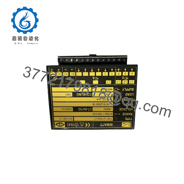
TAP-210DG/3
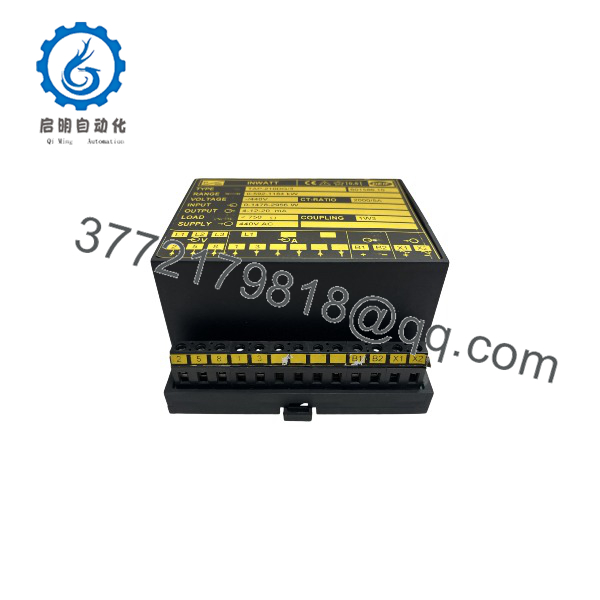
TAP-210DG/3
System Compatibility & Integration Requirements
| Integration item | Requirement |
|---|---|
| Electrical network | Select the appropriate single-phase or three-phase connection configuration |
| Current transformer | Match the configured secondary current and primary-to-secondary ratio |
| Voltage transformer | Match the configured voltage transformer ratio where applicable |
| Analog receiving equipment | Match the selected current or voltage output signal |
| Power measurement range | Configure according to the nominal network voltage and primary current |
| Auxiliary supply | Match the auxiliary voltage specified for the individual unit |
| Installation | DIN rail mounting |
Replacement considerations
Before installing a replacement TAP-210DG/3, compare the following information with the existing nameplate:
- DEIF order number and connection designation.
- Measuring range and engineering units.
- Current transformer ratio.
- Voltage transformer ratio.
- Auxiliary supply voltage.
- Analog output range and polarity.
A matching model-family designation alone does not establish electrical interchangeability.
Dimensions, Mounting & Connection Notes
The TAP-210DG/3 is designed for DIN rail mounting.
Installation considerations:
- Maintain adequate spacing between adjacent transducers.
- DEIF recommends a 30 mm distance between mounted units.
- Use the designated screw terminals for electrical connections.
- Select conductor sizes according to the applicable terminal specifications.
- Provide sufficient ventilation around the installed device.
- Follow the designated connection diagram for the selected measurement configuration.
The documented terminal conductor capacities are:
| Conductor type | Maximum cross-sectional area |
|---|---|
| Multistranded | 2.5 mm² |
| Single-stranded | 4.0 mm² |
Frequently Asked Questions
Q1: What is the DEIF TAP-210DG/3?
The DEIF TAP-210DG/3 is an AC active-power transducer that measures electrical wattage and converts the measurement into a proportional analog output signal.
Q2: Can the TAP-210DG/3 measure three-phase power?
Yes. It supports three-phase, three-wire and four-wire measurement configurations, with different connection options for balanced and unbalanced loads.
Q3: What output signals are available?
Documented output options include 0–20 mA, 4–20 mA, 0–10 V and several other current and voltage ranges. The actual output depends on the ordered configuration.
Q4: What is the measurement accuracy of the TAP-210DG/3?
The documented measurement accuracy is Class 0.5.
Q5: How is the TAP-210DG/3 installed?
The transducer is designed for DIN rail mounting. Electrical connections are made through screw terminals according to the selected wiring configuration.
Q6: What information is needed when replacing an existing TAP-210DG/3?
Check the connection designation, measuring range, current transformer ratio, voltage transformer ratio, auxiliary supply, and analog output signal. These parameters determine whether the replacement matches the existing measurement circuit.
Q7: Can the TAP-210DG/3 connect to a PLC?
Its analog output can be connected to a PLC analog input when the output signal type, input range, electrical loading, and signal scaling are compatible.