
 WhatsApp: +86 16626708626
 Email:
  Phone: +86 16626708626
Description
Key Technical Specifications
| Parameter | Value |
|---|---|
| Manufacturer | Delta Tau Data Systems; later Omron motion-control family |
| Model | ACC-24E2S |
| Board Reference | 3Ax-603441-xUxx |
| Product Type | Four-channel encoder and stepper axis interface board |
| Product Family | UMAC / Turbo PMAC / MACRO Station accessory |
| Rack Format | 3U UMAC industrial rack |
| System Interface | 96-pin UBUS backplane connector |
| Motion Channels | 4 channels per board |
| Primary Output Type | TTL-level pulse-frequency-modulation (PFM) stepper output |
| Motor-Control Use | Stepper drives using differential pulse and direction signals |
| Encoder Feedback | Incremental quadrature encoder input, A/B with optional index |
| Encoder Input Format | Differential or single-ended, configurable through resistor-pack arrangement |
| Encoder Signal Level | TTL-level inputs |
| Encoder-Loss Detection | Supported with correct differential-input resistor-pack configuration |
| Position-Limit / Flag Inputs | Supports 12–24 V DC sensors or limit switches |
| Limit/Flag Type | Sinking or sourcing field devices supported through opto-isolated input circuitry |
| Position Compare Outputs | Four compare outputs; fast CMOS driver operation |
| Position Compare Timing | Specified firing within 100 ns of commanded position |
| Compare Output Driver | DS75451N fast CMOS driver |
| Compare Output Rating | 5 V, 10 mA maximum, totem-pole CMOS |
| Compare Output Frequency | Up to 5 MHz |
| Required Power | +5 V DC at 0.9 A, ±10% |
| UMAC Capacity | Up to 8 ACC-24E2S boards; up to 32 additional stepper-interface channels |
| MACRO Station Capacity | Up to 2 ACC-24E2S boards; up to 8 channels of servo data |
| Output Modes in Firmware | Direct PWM, DAC, and PFM selections exist; ACC-24E2S hardware is dedicated to PFM stepper use |
| Connector Options | Phoenix Contact terminal blocks or optional DB15 connectors |
| Environmental / Safety References | CE, UL 61010-1, CAN/CSA C22.2 No. 1010.1-92, UL 94V-0 stated in product manual |
| Lifecycle Status | Legacy motion-control accessory; verify availability, hardware revision, and controller compatibility before ordering |
Delta Tau documents the ACC-24E2S as a four-channel encoder/stepper axis-interface board for UMAC and MACRO Station systems. It uses a 5 V DC supply rated at 0.9 A, provides up to four channels per card, and can expand a UMAC system by as many as 32 stepper-interface channels when eight boards are installed.
Product Introduction
The Delta Tau ACC-24E2S is a 3U UMAC axis expansion card for applications that require four stepper-drive interfaces with encoder feedback. It connects to UMAC, Turbo UMAC, Ultralite, and MACRO Station motion systems through the UBUS backplane, providing TTL-level differential pulse-and-direction outputs, incremental encoder inputs, limit inputs, home inputs, flags, amplifier enables, and position-compare outputs.
The is the dedicated four-channel stepper version of the ACC-24E2 family. It is not interchangeable with the ACC-24E2 direct-PWM servo card or the ACC-24E2A analog ±10 V interface card. Confirm the UMAC CPU type, firmware revision, S1 address setting, clock jumper arrangement, connector option, encoder type, and stepper-drive input requirements before installation.
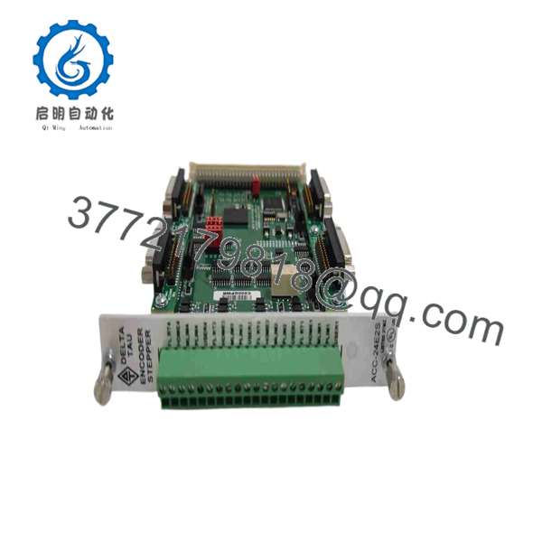
ACC-24E2S
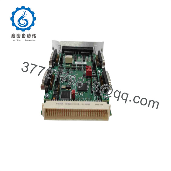
ACC-24E2S
Troubleshooting Quick Reference
| Symptom | Possible Cause | Relevance to this Part | Quick Check Method | Recommendation |
|---|---|---|---|---|
| No board LEDs or no UMAC recognition | Missing +5 V backplane power, unseated card, defective rack PSU, failed board | ⚠️ Medium | Measure +5 V DC at the UBUS backplane; inspect card seating and edge connector; verify the rack supply remains within ±10% under load | Confirm backplane power first. The requires approximately 0.9 A from the +5 V rail |
| Stepper drive does not move | Drive inhibit active, missing pulse/direction signals, wrong output mode, wiring error | ⚠️ Medium | Measure differential pulse and direction outputs at the connector with an oscilloscope while issuing a low-speed jog | Check drive enable, output wiring, and PMAC configuration before replacing the board |
| Motor moves but only in one direction | Direction pair wiring fault, incorrect drive input mode, polarity mismatch | ❌ Low | Monitor both Direction+ and Direction− signals while commanding positive and negative jogs | Correct the wiring or drive configuration. This is usually external to the |
| Motor runs at incorrect speed | Pulse scaling error, wrong steps-per-revolution setting, output frequency limit, incorrect motor parameters | ❌ Low | Compare commanded speed with pulse frequency using an oscilloscope; verify motor step angle, microstep setting, gear ratio, and software scaling | Correct PMAC motor parameters and drive settings; do not replace the board for a scaling issue |
| Encoder position stays at zero | Failed encoder, missing encoder supply, A/B lines disconnected, resistor-pack mismatch | ⚠️ Medium | Check encoder supply, then verify A/A̅ and B/B̅ transitions at the board connector; inspect TB or DB15 termination points | Confirm known-good encoder signals reach the board before replacing it |
| Following error or position loss occurs during motion | Encoder noise, loose terminal, poor shielding, incorrect differential termination, damaged encoder cable | ⚠️ Medium | Trend counts while flexing the cable; inspect shielding and connector torque; use an oscilloscope to check differential signal quality | Repair wiring and grounding first. Differential feedback is preferred for long or electrically noisy cable runs |
| Random limit or home input alarms | Incorrect sinking/sourcing wiring, bad 12–24 V sensor, shared common issue, noisy field wiring | ❌ Low | Measure voltage at the front limit/flag terminals while activating each sensor; compare the sensor wiring to the input schematic | Verify sourcing versus sinking configuration. The board supports both, but the field wiring must match |
| Stepper motor does not enable | Amplifier-enable pair not present, drive safety circuit open, interlock not reset | ⚠️ Medium | Measure AENA+/AENA− at the drive input when the axis is commanded enabled; check drive fault and safety relay status | Resolve drive faults and external safety interlocks before replacing the motion card |
| Replacement board creates watchdog or timing faults | Incorrect servo/phase clock jumper setting, address duplication, UBUS setup conflict | ✅ High | Compare the old board’s S1 DIP switch and clock jumper positions; confirm there is only one configured source for phase and servo clocks | Photograph the removed card before replacement. Restore the exact address and clock settings unless the system design has changed |
| Multiple axes fail after a card swap | Duplicate S1 address, wrong Servo IC assignment, firmware configuration mismatch | ✅ High | Check all installed accessory-card addresses and the controller’s recognized Servo IC configuration after power-up | Set a unique S1 address and verify firmware variables before enabling any axis |
| Position compare output does not fire | Incorrect compare configuration, output wiring issue, overloaded compare output | ⚠️ Medium | Check compare output at the terminal with an oscilloscope; verify the programmed compare position and external load current | Keep compare loading within 5 V and 10 mA maximum. Use an external buffer or relay interface for larger loads |
| Card works briefly, then faults after cabinet warms up | Rack temperature too high, weak 5 V supply, intermittent connector contact, aging electronics | ⚠️ Medium | Trend +5 V DC and cabinet temperature during operation; inspect rack retention and UBUS connector engagement | Correct power and cooling issues first. Replace the board only after the environment is verified |
❗ Clock-jumper warning: Each UMAC system can have only one phase-clock and servo-clock source. Incorrect clock settings can create timing conflicts or a watchdog condition across several axes, not just the replaced card. Copy the old board’s clock configuration before removal.
❗ S1 address warning: The S1 DIP switch controls board addressing and the related Servo IC configuration. A duplicate or incorrect setting can make the controller assign the wrong axis channels after startup. Take a close photo before you touch anything.
❗ Stepper-output warning: The is built for PFM stepper operation. Its manual lists multiple software output-mode selections, but the board’s hardware limitations mean it should be used only for PFM output. Do not substitute it for an analog-output or direct-PWM servo board.
❗ ESD warning: Wear a grounded wrist strap and keep the board in ESD-safe packaging until installation. I have watched a technician handle a motion card without a strap on a dry day, power it up, and then chase a dead encoder channel for the rest of the shift. Use the strap.
If you need support, send clear photos of the front label, S1 address switches, clock jumpers, UMAC rack slot, encoder and drive connectors, LED states, stepper-drive fault display, and PMAC diagnostic or following-error logs.
Frequently Asked Questions
What is the Delta Tau used for?
The adds four stepper-motion channels and encoder-feedback channels to a UMAC or MACRO Station system. It is used where a Delta Tau PMAC-family controller must operate stepper drives through TTL-level pulse-and-direction signals while receiving incremental encoder feedback, limits, home sensors, flags, and position-compare events.
Is the a servo-drive interface card?
Not in the same way as the ACC-24E2 or ACC-24E2A. The is the dedicated stepper interface card. The ACC-24E2 supports direct PWM servo-amplifier control, while the ACC-24E2A supports analog ±10 V servo interfaces. The outputs pulse-frequency-modulation signals for stepper applications.
How many stepper axes does one support?
One supports four channels. A UMAC can use up to eight boards for up to 32 additional stepper-interface channels. A MACRO Station CPU can service only eight servo-data channels, so it supports up to two boards in the documented configuration.
Can I hot-swap an board?
No. Treat it as a powered motion-control expansion board, not a hot-swappable I/O module. Shut down the rack according to the machine’s lockout/tagout procedure, discharge static, save the PMAC configuration, and photograph every switch and connector before removal. Pulling it under power can cause UBUS faults, damage the board or backplane, and generate unexpected motion-system alarms.
What must I record before replacing the board?
Document the full model and board revision, S1 DIP-switch address, phase/servo clock jumper settings, encoder resistor-pack arrangement, terminal-block or DB15 connector option, PMAC CPU type, controller firmware version, stepper-drive model, motor scaling, pulse frequency limits, enabled axis mapping, and all relevant PMAC I-variables or MACRO MI-variables. That information prevents the most common replacement failure: a healthy board installed with the wrong hardware or software configuration.
Why does the new power up but not move the motors?
Most of the time, the board is not the root cause. Check the drive’s enable and fault circuits, pulse/direction signal wiring, output mode, motor parameter scaling, controller configuration, and safety interlocks. Then use an oscilloscope to confirm differential pulse and direction signals reach the drive while issuing a low-speed jog. If those signals are absent with a confirmed controller command, investigate the card configuration and board hardware.
Can I use single-ended encoders with the ?
Yes, the board can be configured for differential or single-ended encoder feedback. Differential feedback is usually the safer choice for long cables or installations near VFDs, contactors, and servo amplifiers because it rejects common-mode electrical noise better. Match the resistor-pack configuration to the encoder type, and inspect the existing configuration rather than assuming factory defaults apply.
Is the obsolete?
It is part of the legacy Delta Tau UMAC/Turbo PMAC accessory ecosystem, so availability should be treated as limited and stock-dependent. The later Power UMAC platform lists the among legacy-compatible axis interface options, while the newer ACC-24E3 provides a different Gate3-style motion-interface approach. The ACC-24E3 is not a guaranteed drop-in replacement; it requires a compatibility and migration review.
What condition should I require for a production spare?
For a production-critical spare, request New Original / New Surplus with photos of the original label, connectors, and packaging, or Refurbished (tested) with proof of operation in a compatible UMAC rack. A useful test should verify +5 V power draw, UBUS recognition, all four pulse/direction outputs, encoder counting, limit and flag inputs, amplifier-enable outputs, position-compare operation, and sustained run time. Request test photos or video, exact stock confirmation, lead time, and written warranty before placing the order.



