
 WhatsApp: +86 16626708626
 Email:
  Phone: +86 16626708626
Description
Key Technical Specifications
| Parameter | Specification |
|---|---|
| Model | ACC-36E |
| Manufacturer | Delta Tau Data Systems |
| Product Type | Analog I/O / data acquisition board |
| Analog Inputs | 16 channels |
| ADC Resolution | 12 bit |
| ADC Device | Maxim MAX180 |
| ADC Architecture | Multiplexed |
| Input Configuration | Single-ended or differential |
| Unipolar Range | 0 to 20 V single-ended; 0 to 10 V differential |
| Bipolar Range | -10 to +10 V single-ended; -5 to +5 V differential |
| Host Interface | UMAC processor bus / 3U backplane |
| Host Systems | UMAC Turbo PMAC, Power PMAC, MACRO-related configurations |
| Feedback Use | Analog servo feedback supported |
| Sensor Supply | Approximately +12 V and -12 V outputs; 0.5 A maximum per supply line |
| Base Configuration | Channels 1–8 |
| Option 1 | Channels 9–16 |
| Board Addressing | DIP-switch selectable |
| ADC Linearity | ±1/2 LSB |
| Board Type | 3U rack-mounted accessory |
The documented ACC-36E uses MAX180 12-bit ADC devices and multiplexes the analog inputs. The standard board provides 16 analog channels, while the controller reads the selected ADC channels through the UMAC processor bus.
The input ranges are configurable for unipolar or bipolar operation. Delta Tau documentation specifies 0–20 V single-ended / 0–10 V differential for unipolar operation and -10 to +10 V single-ended / -5 to +5 V differential for bipolar operation.
Product Introduction
The Delta Tau ACC-36E is a 16-channel, 12-bit analog input board for UMAC and related Delta Tau motion-control platforms. It converts sensor or transducer voltage signals into digital values that can be accessed by UMAC software, PLC programs, M-variables, or the encoder conversion table.
A useful feature for legacy motion systems is its ability to use analog inputs as feedback devices in addition to general data acquisition. The board supports both single-ended and differential wiring, with selectable unipolar and bipolar signal ranges.
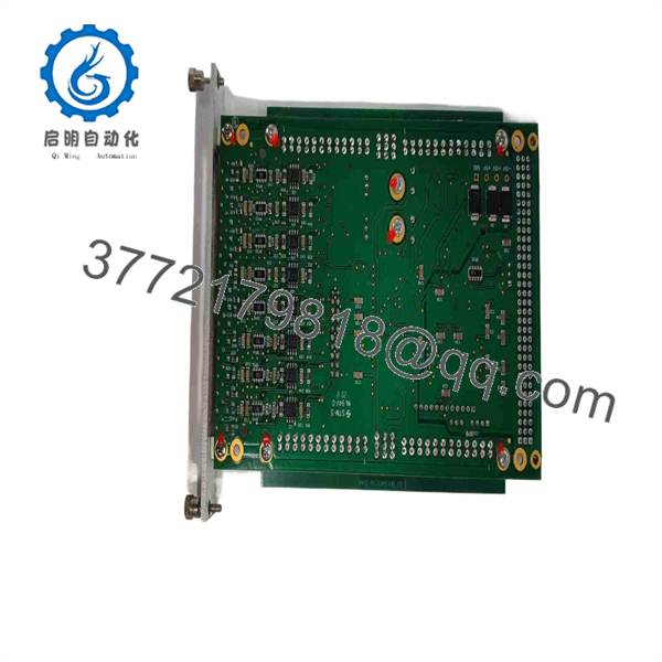
ACC-36E
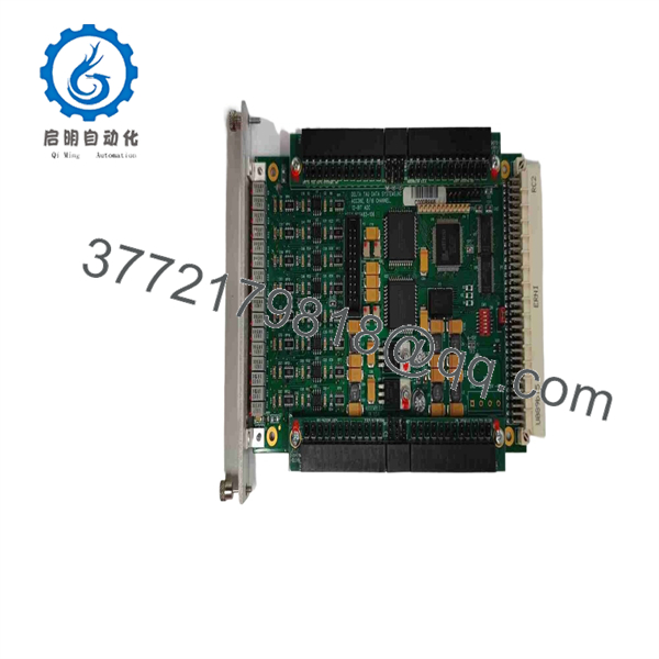
ACC-36E
Installation & Configuration Guide
Stage 1 — Pre-Installation Preparation (~10 min)
- Confirm the replacement is ACC-36E, including the board revision and option configuration.
- Verify the UMAC/Turbo PMAC or Power PMAC hardware configuration.
- Back up the controller configuration, PLC programs, M-variable definitions, and ADC-related settings.
- Record the board address selected by DIP switch SW1.
- Identify whether each field signal is wired single-ended or differential.
- ⚠️ Power down the UMAC rack and follow the machine’s lockout/tagout procedure before removing the card.
Stage 2 — Removing the Old Module (~5 min)
- Switch off system power and verify that the rack is de-energized.
- Label each analog input connector before disconnecting it.
- Disconnect the J1–J4 field connections as applicable.
- Release the rack retention hardware and remove the ACC-36E from the backplane.
- Inspect the backplane connector and field wiring for contamination, bent contacts, or damaged insulation.
- Record the original DIP-switch and jumper positions before installing the replacement.
Stage 3 — Installing the New Module (~5 min)
- ⚠️ Use ESD protection when handling the ACC-36E.
- Confirm that the replacement board matches the required configuration.
- Set the board address to match the controller configuration.
- Verify the E-point jumper and other configuration positions against the existing installation.
- Insert the card into the correct 3U UMAC rack position.
- Reconnect the analog channels according to the original wiring documentation.
- Confirm that differential inputs have both positive and negative signal connections where required.
- Check that external sensor loads do not exceed the board’s documented auxiliary supply limits.
Stage 4 — Power-On & Testing (~10–15 min)
- Restore rack power and check for abnormal hardware indications.
- Confirm that the UMAC/Power PMAC recognizes the at the configured address.
- Verify one known analog input before commissioning all channels.
- Check the raw ADC value against the actual field voltage using an appropriate meter.
- Confirm the selected unipolar/bipolar interpretation matches the controller configuration.
- For feedback applications, verify the signal direction and scaling before enabling motion.
- Test each required channel individually.
- ⚠️ Do not enable closed-loop motion until the analog feedback value, polarity, scaling, and loss-of-signal behavior have been verified.
FAQ
What is the Delta Tau used for?
The is primarily a 16-channel analog data acquisition board. It converts external analog voltage signals into 12-bit digital values for use by UMAC control software and PLC programs. It can also be used as an analog feedback source for motion-control applications.
How many analog inputs does the provide?
The provides 16 analog input channels. The ADCs are multiplexed, so the controller selects the channel or channel pair to be converted.
What voltage ranges are supported?
The documented configurations include 0–20 V single-ended, 0–10 V differential, -10 to +10 V single-ended, and -5 to +5 V differential. The correct configuration depends on the input mode selected for the application.
Can the be used for servo feedback?
Yes. Delta Tau documentation specifically describes using analog inputs as feedback devices. The converted values can be placed into UMAC memory and used through the encoder conversion table for servo-feedback applications.
Is compatible with Power PMAC?
Yes. Current Power PMAC software documentation includes dedicated status structures, identifying the board as a 16-channel, 12-bit multiplexed A/D converter board for UMAC systems.
What should I check before replacing an ?
Check the exact board model/revision, rack position, address DIP switch, jumper settings, input wiring, signal range, and UMAC configuration. For a machine using as servo feedback, also verify the ADC scaling and polarity before enabling motion.
Does the supply power to connected sensors?
The board provides auxiliary positive and negative supply outputs through its analog connectors. The documented design limits the current to 0.5 A per supply line. These outputs should not be treated as a general-purpose power supply.



