
 WhatsApp: +86 16626708626
 Email:
  Phone: +86 16626708626
Description
Key Technical Specifications
| Parameter | Value |
|---|---|
| Manufacturer | Delta Tau Data Systems; later Omron PMAC family |
| Model | ACC-68E |
| Product Type | UMAC digital I/O expansion board |
| I/O Architecture | Isolated, self-protected sinking digital I/O |
| Digital Inputs | 24 |
| Digital Outputs | 24 |
| Total I/O Points | 48 |
| Field Voltage | 12–24 V DC |
| Input Type | Isolated NPN/sinking-compatible inputs |
| Output Type | Isolated sinking outputs |
| Output Protection | Self-protected against overcurrent and related field faults |
| Output Current | Verify the exact board manual and label; legacy UMAC documentation identifies this family as self-protected field I/O |
| Controller Compatibility | UMAC, Turbo UMAC, Turbo PMAC, and compatible Power UMAC architectures |
| I/O ASIC | PMAC2-style IOGATE |
| Rack Format | 3U UMAC Eurocard |
| Backplane Interface | UBUS |
| Field Connection | Terminal-block version or optional female DB-15 connector |
| Input/Output Isolation | Optically isolated field channels |
| Board Addressing | Hardware address selection through the board’s address switch configuration |
| Power Source | UMAC rack/backplane supply; verify board-specific current requirement from the exact hardware revision |
| Installation | UMAC modular rack expansion slot |
| Lifecycle Status | Legacy/obsolete accessory; confirm exact revision and stock condition before purchase |
Delta Tau’s UMAC selection documentation identifies the ACC-68E as an isolated, self-protected sinking board with 24 inputs and 24 outputs for 12–24 V DC field devices. Omron’s PMAC catalog lists the same board as a 24-input/24-output, isolated NPN-type module with terminal-block or optional female DB-15 connection.
Product Introduction
The Delta Tau ACC-68E is a UMAC digital I/O expansion board that provides 24 isolated digital inputs and 24 isolated digital outputs for 12–24 V DC machine signals. It is designed for Turbo UMAC, Turbo PMAC, and related PMAC motion-control systems, where it handles sensors, limit switches, pushbuttons, solenoids, relays, drive status signals, and other discrete machine interfaces.
This board uses sinking/NPN-style field wiring and self-protected I/O circuits, making it different from the sourcing ACC-65E and ACC-67E boards. Confirm the field-device polarity, output load current, board address, connector option, UBUS rack compatibility, and controller configuration before installation. Do not substitute a sourcing card because the part numbers look similar.
Troubleshooting Quick Reference
| Symptom | Possible Cause | Relevance to this Part | Quick Check Method | Recommendation |
|---|---|---|---|---|
| Entire board is absent from the UMAC system | Missing backplane power, poor card seating, incorrect address, failed UBUS interface | ⚠️ Medium | Power down and reseat the card; inspect the UBUS connector; verify the board address and rack supply before checking software recognition | Check rack power and addressing first. A single configuration error can make a healthy I/O board appear missing |
| All inputs read inactive | Missing field supply, incorrect NPN wiring, common connection open, wrong input reference | ⚠️ Medium | Measure 12–24 V DC at the input common and the field device; activate one known-good sensor and measure the input terminal voltage | Confirm the field supply and sinking arrangement. Do not replace the card until one known-good input circuit has been proven |
| One input remains active | Shorted input wire, failed sensor, incorrect common, damaged input channel | ❌ Low | Disconnect the field wire under an approved procedure and check whether the software input changes; measure the terminal for unexpected voltage | Isolate the field wiring first. A shorted sensor or wet cable is more likely than an input-board failure |
| Inputs flicker during machine operation | Electrical noise, poor shield/grounding, unstable 24 V DC supply, loose terminal | ⚠️ Medium | Monitor the 24 V DC field supply while contactors or drives operate; inspect terminal torque and shield termination | Correct wiring, grounding, or power-quality problems before replacing the ACC-68E |
| Output command is present but load does not energize | Wrong sinking/sourcing expectation, open field supply, load wired to the wrong common, blown external fuse | ⚠️ Medium | Command a noncritical output and measure voltage at the output terminal relative to the field supply common; verify the load return path | Confirm that the load is wired for a sinking output. The ACC-68E is not a drop-in replacement for a sourcing output board |
| Output immediately turns off | Overcurrent protection, shorted solenoid, incorrect load, field wiring fault | ✅ High | Disconnect the load, reset the output, and measure the load resistance; inspect for a shorted coil or damaged cable | Repair the field short first. Self-protection is intended to limit damage, not to replace correct circuit protection |
| Several outputs fail on one group | Shared supply fuse open, common return disconnected, group wiring fault, overloaded supply | ❌ Low | Measure field voltage at the common terminal and check the external fuse; test an output with a current-limited lamp or approved test load | Restore the shared supply/common connection before condemning the board |
| Output remains energized after the PLC command turns off | Stuck software bit, output transistor fault, wiring bypass, incorrect output mapping | ⚠️ Medium | Remove the field conductor under controlled conditions and compare terminal state with the software command | If the terminal remains active with the command off and field wiring isolated, the output channel may require board replacement |
| Replacement board powers up but I/O mapping is wrong | Incorrect board address, wrong base address, controller configuration mismatch | ✅ High | Compare the old board’s address switch and the controller’s I/O variable map; test one input and one output by known point | Copy the original address and verify the PMAC/UMAC I/O configuration before connecting the machine |
| Input device works on a sourcing card but not on ACC-68E | PNP/NPN polarity mismatch | ✅ High | Identify whether the sensor sources voltage or sinks current; compare its wiring diagram with the input circuit | Use an NPN-compatible wiring arrangement or select the correct sourcing I/O board. Do not bridge polarity differences with improvised wiring |
| Board trips after a replacement field device is connected | Inrush current, shorted coil, incorrect suppression, output overload | ⚠️ Medium | Connect the field device through a current-limited test supply; measure steady-state and inrush current | Use the correct suppression and load rating. Verify the exact output-current specification for the board revision |
| I/O faults appear after a card swap | Wrong connector pinout, terminal block option mismatch, wiring shifted by one position | ✅ High | Photograph and label every conductor before removal; compare terminal numbering and connector keying against the manual | Never transfer wires by memory. Verify each point against the manual and the original board label |
❗ Polarity warning: The is the sinking/NPN member of the UMAC I/O family. The ACC-65E and ACC-67E use sourcing/PNP-style field interfaces. A card can fit the same rack and still be electrically wrong for the machine.
❗ Output-load warning: The self-protection circuit is not permission to connect an oversized solenoid, motor contactor coil, or unprotected inductive load. Verify load current, suppression, common wiring, and external fusing before commissioning.
❗ Address warning: Photograph the board address switch before removal. A replacement with the wrong address can shift every input and output point in the controller map, causing dangerous-looking symptoms that are actually configuration errors.
If the problem persists, provide technical support with photos of the label, board address switch, terminal blocks or DB-15 connector, field power supply, connected sensor/actuator wiring, UMAC rack slot, I/O status, and controller diagnostic variables.
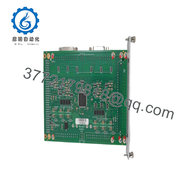
ACC-68E
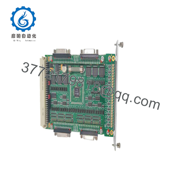
ACC-68E
Frequently Asked Questions
What does the Delta Tau do?
The provides 24 isolated digital inputs and 24 isolated digital outputs for a UMAC or Turbo PMAC system. It is used for discrete machine signals such as proximity sensors, limit switches, pushbuttons, drive-ready contacts, solenoids, relays, and actuator commands. Delta Tau identifies it as an isolated, self-protected sinking 24-input/24-output board.
Is the a sourcing or sinking I/O board?
It is a sinking/NPN-style board. The is intended for field devices and loads wired to the corresponding sinking input/output arrangement. The sourcing equivalents in the same family include the ACC-65E and ACC-67E. Check the sensor and actuator wiring diagrams before ordering; matching the connector and number of I/O points is not enough.
Can I replace an with an ACC-65E or ACC-67E?
Not as a direct electrical substitution. The ACC-65E provides sourcing 24 inputs and 24 outputs, while the ACC-67E provides sourcing outputs. The provides sinking 24 inputs and 24 outputs. The controller software may also require different I/O polarity and point configuration. Choose the replacement based on field polarity, not just the UMAC rack fit.
What voltage does the use?
The field I/O operates in the 12–24 V DC range. The Omron PMAC catalog lists the as a 12–24 V DC isolated NPN-type module. Verify the exact board label and connected device requirements, especially when the existing rack includes mixed 12 V DC and 24 V DC circuits.
Can I hot-swap the ?
Do not assume that it is hot-swappable. Remove power according to the machine’s lockout/tagout procedure before extracting the UBUS card. Live removal can disturb the backplane, create unexpected output states, damage the board connector, or expose the I/O electronics to ESD. De-energize field outputs and document wiring before replacement.
What must I record before replacing the ?
Record the complete model and revision, board address switch setting, connector type, UMAC rack slot, terminal numbering, input/output point map, field supply voltage, NPN sensor wiring, output load type, external fuse ratings, and controller firmware/configuration. Photograph every terminal before removal. This is especially important when a terminal-block module is replaced with a DB-15 version or when the replacement has a different board revision.
Why do my sensors work with another I/O card but not with the ?
The most likely reason is polarity mismatch. A sensor that sources voltage, such as a PNP sensor, may not operate correctly on a sinking/NPN input arrangement without the correct wiring interface. Check the sensor output type, common connection, and input circuit. Do not assume a 24 V sensor is compatible merely because its voltage rating matches.
Why does an output trip as soon as I turn it on?
A shorted solenoid, damaged cable, excessive inrush, incorrect common wiring, or missing suppression can trigger the ’s self-protection. Disconnect the load, reset the output, and test the channel with a suitable current-limited load. If the output works unloaded but trips with the actuator attached, repair or replace the field device before replacing the board.
Is the obsolete?
The belongs to the legacy Delta Tau UMAC/Turbo PMAC accessory family, so availability and support should be treated as limited. Omron documentation continues to list the model in PMAC accessory information, but current UMAC installations may require lifecycle planning and verified spare stock. Do not assume a newer Power UMAC digital-I/O option is mechanically or electrically interchangeable.
What condition should I request for a production spare?
Request New Original / New Surplus with photos of the label, connector, packaging, and board revision, or Refurbished (tested) with a documented I/O test. A meaningful test should power the unit in a compatible UMAC rack, verify board recognition and addressing, test all 24 inputs with 12–24 V DC signals, switch all 24 outputs into suitable loads, confirm overcurrent protection behavior, and record the test date. Get written warranty and return terms before purchase.



