
 WhatsApp: +86 16626708626
 Email:
  Phone: +86 16626708626
Description
Key Technical Specifications
| Parameter | Value |
|---|---|
| Manufacturer | Delta Tau Data Systems |
| Model Number | CLIPPERT3 |
| Common Product Name | Turbo Clipper T3 |
| Product Family | Turbo PMAC / Clipper |
| Product Type | Embedded multi-axis motion controller |
| Base Motion Capacity | 4 servo or stepper axes |
| Primary Processor | Motorola DSP56303 |
| Processor Clock | 80 MHz |
| User Memory | 256K × 24-bit SRAM |
| Flash Memory | 1M × 8-bit flash |
| Servo Output | 12-bit ±10 V analog command output per base axis |
| Alternate Axis Output | Pulse-and-direction outputs |
| Feedback Interface | Differential or single-ended encoder inputs; Hall-effect feedback support |
| Digital I/O | 32 TTL-level general-purpose I/O points |
| Handwheel Support | Dual quadrature encoder inputs and pulse-output pairs |
| Communications | 100 Mbps Ethernet, RS-232 serial, USB 2.0 |
| Expansion Support | Additional axes, ADC/DAC, PWM, and specialty I/O through compatible accessory boards |
| Power Requirements | +5 V logic supply and ±12 V analog supply through a 4-pin Molex power connection |
| Board Dimensions | Approximately 110 × 220 mm / 4.25 × 8.5 in. |
| Mounting | Board-level or chassis/panel installation with standoffs, grounding, and airflow |
| Replacement Requirement | Match controller label, firmware, Turbo PMAC application program, I/O wiring, feedback type, expansion cards, and host communications configuration |
Market references consistently identify CLIPPERT3 as a Delta Tau Turbo Clipper T3 multi-axis motion controller within the Turbo PMAC family. However, published reseller details conflict on processor, I/O, and physical specifications, so the complete board label, installed firmware, connector arrangement, and original machine documentation must control final procurement.
Product Introduction
Delta Tau CLIPPERT3, commonly called Turbo Clipper T3, is an embedded multi-axis motion controller for machines that require coordinated servo or stepper control. Typical uses include CNC machinery, positioning systems, packaging equipment, semiconductor tools, robotics, printing equipment, and custom machine automation.
The controller runs motion calculations locally and interfaces with servo amplifiers through ±10 V analog commands or pulse-and-direction signals. It is not a general-purpose PLC replacement. The safe replacement path is to duplicate the original Turbo PMAC program, firmware, feedback wiring, I/O mapping, expansion hardware, and host communications settings.
Troubleshooting Quick Reference
| Symptom | Possible Cause | Relevance to This Part | Quick Check Method | Recommendation |
|---|---|---|---|---|
| Controller shows no power or no communication | Missing +5 V supply, missing ±12 V analog supply, blown fuse, loose Molex connector, incorrect power polarity | ✅ High | Measure +5 V DC and ±12 V DC at the controller power connector against the machine electrical drawing; verify common ground and upstream fuse condition | Correct the power supply or wiring first. Do not install a replacement board until supply voltages are verified under load. |
| Controller powers up but host PC cannot connect | Incorrect Ethernet IP address, wrong subnet, serial settings mismatch, damaged cable, host firewall, firmware or protocol mismatch | ✅ High | Check Ethernet link status, ping the known IP address, verify host IP/subnet, and compare RS-232 baud rate, parity, data bits, stop bits, and cable wiring | Restore communications parameters from the old controller backup before replacing hardware. |
| One axis does not enable | Drive enable interlock open, external E-stop active, amplifier fault, broken command cable, incorrect I/O mapping | ✅ Medium | Check E-stop chain, amplifier fault output, enable signal, and controller digital I/O state; measure command output while issuing a low-speed jog | Diagnose the servo amplifier and safety chain before replacing CLIPPERT3. |
| Axis runs away or moves unexpectedly | Encoder polarity error, motor phase feedback mismatch, incorrect gains, incorrect coordinate system, corrupted program | ✅ High | Disable machine motion safely; verify encoder A/B/Z wiring and feedback direction; compare servo gains, axis definitions, and program files to the original backup | Do not tune a replacement from scratch on a live machine. Restore verified parameters and test at limited speed. |
| Axis moves in the wrong direction | Motor direction reversed, encoder direction inverted, sign error in configuration, wrong servo amplifier setup | ❌ Low | Command a controlled low-speed move; inspect position count direction and analog-command polarity with the machine isolated | Correct the axis configuration or amplifier direction setting. Do not interchange motor leads without reviewing the drive documentation. |
| Position drifts or following error grows | Encoder cable noise, loose coupling, failed encoder, poor shield grounding, gain issue, mechanical backlash | ✅ Medium | Trend commanded versus actual position; inspect encoder waveform and shield bonding; check coupling, bearings, belts, and load mechanics | Separate mechanical feedback faults from controller faults before replacing the board. |
| Multiple axes fail after a board swap | Wrong Turbo PMAC program, missing firmware options, expansion card not installed, configuration not restored | ✅ High | Compare old and new controller firmware, flash contents, board jumpers, installed expansion cards, and configuration files | Back up the old controller before removal. Load the validated machine program and verify all axes one at a time. |
| Analog command remains at 0 V | Axis disabled, controller not executing, DAC supply missing, output cable open, program interlock active | ✅ High | Measure the relevant ±10 V command output at the controller connector during a jog command; check ±12 V analog supply and axis-enable logic | Verify software status and power rails. Replace the controller only if a known-good configured axis produces no command output. |
| Digital I/O does not change state | Wrong I/O address, TTL-level incompatibility, missing common reference, external I/O board fault, damaged interface | ✅ Medium | Read I/O state through the host diagnostic utility; measure signal level at the controller pin and at the field interface | Check voltage-level compatibility and external interface hardware. Do not connect 24 V field I/O directly to TTL I/O without the specified interface. |
| Replacement board boots but loses settings | Battery or nonvolatile-memory problem, wrong firmware, damaged flash, configuration not saved | ✅ High | Power-cycle the controller after loading the configuration; verify memory retention and compare checksums or saved program revision | Replace or service the controller if settings cannot be retained after configuration is confirmed. |
❗ Firmware and application warning: The board alone does not make the machine run. Turbo PMAC program files, coordinate-system setup, servo gains, I/O assignments, homing routines, PLC logic inside the motion application, and host communications settings are part of the machine. Back up the old controller before removal. I have seen a replacement board pass a bench boot test and still keep a machine down for days because the original application files were never archived.
❗ DIP-switch and jumper warning: Photograph every jumper, address selector, daughterboard, expansion card, cable orientation, and connector label before touching the controller. It is the most common rookie mistake, and it happens constantly. Take a picture before you touch anything. Seriously.
❗ Encoder warning: A reversed encoder channel or wrong differential/single-ended interface can create a runaway-axis condition. Start replacement commissioning with mechanical load isolated where possible, low speed limits, low torque limits, active E-stop access, and a verified safe test procedure.
❗ TTL I/O warning: The listed digital I/O is TTL-level, not automatically 24 V DC PLC I/O. Connecting 24 V directly to a TTL point can destroy the controller interface. Verify each signal through the machine schematic and use the correct opto-isolated or level-conversion interface.
❗ Power warning: The controller requires both logic and analog power rails in the cited configuration: +5 V and ±12 V. A board may communicate normally on +5 V yet produce no valid analog servo command when the ±12 V rail is missing or low. Measure all rails under load.
❗ ESD warning: Use a grounded wrist strap and ESD mat. Motion boards contain sensitive DSP, memory, encoder, and communications circuitry. I once watched a replacement board get handled on an unprotected bench in dry weather; it booted but lost an encoder channel during commissioning. The spare was ruined before the machine ever moved.
Keep these checks in mind and you will save yourself 90% of typical rework time. If the failure is unresolved, provide technical support with full board-label photos, firmware version, program backup, connector photos, power-rail readings, servo-drive fault history, host communication diagnostics, and axis/encoder wiring drawings.

CLIPPERT3
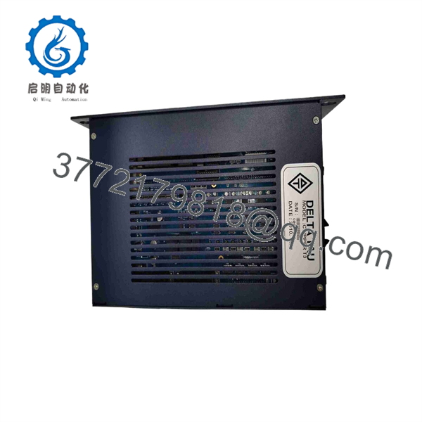
CLIPPERT3
Frequently Asked Questions
What is the Delta Tau CLIPPERT3?
Delta Tau CLIPPERT3, also called Turbo Clipper T3, is an embedded multi-axis motion controller from the Delta Tau Turbo PMAC/Clipper family. It controls coordinated servo or stepper axes and is used in equipment such as CNC machines, robotics, positioning systems, packaging lines, and specialty automation equipment.
Is a PLC?
No. is primarily a motion controller, not a general-purpose PLC CPU. It handles trajectory generation, coordinated motion, feedback processing, axis control, servo tuning, and motion-related I/O. A PLC or industrial PC may still handle sequence logic, machine interlocks, safety functions, operator interface, plant communications, and non-motion I/O.
Do not use a as a replacement for a conventional PLC unless the original machine design specifically uses it that way.
How many axes can control?
Published reseller material commonly describes a base configuration of four servo or stepper axes, with the ability to expand through compatible accessory boards. Since actual capability can depend on installed hardware, firmware, and daughterboards, verify the original controller’s axis count and expansion cards before ordering.
A four-axis board with expansion hardware is not automatically equivalent to a bare four-axis replacement.
Does provide ±10 V servo commands?
Published descriptions commonly list 12-bit ±10 V analog outputs for base servo axes, along with pulse-and-direction alternatives and encoder feedback interfaces. Verify the actual board connectors and machine drawings because revisions and installed options can differ.
Before commissioning, measure a low-speed command with the axis disabled or mechanically safe. A reversed ±10 V command can send the drive in the opposite direction.
Can I hot-swap a motion controller?
No. Shut down machine control power, servo power, and associated DC supplies under the site’s lockout/tagout procedure. A motion controller swap can change servo enable behavior, remove feedback, issue unexpected commands during boot, or leave the system in an undefined state.
To be honest, live replacement of a motion controller is a bad plan. Isolate energy, verify the drives are disabled, secure vertical or gravity-loaded axes, and confirm the machine cannot move before removing connectors.
Will a replacement retain the original motion program?
Do not assume it will. A surplus board may be blank, contain an unknown customer program, have another firmware revision, or be configured for different I/O and communications. The original motion program and parameters may be held in flash, battery-backed memory, or transferred from a host system depending on the machine design.
Before removal, save:
- Turbo PMAC program and PLC code
- Firmware version and option status
- Servo gains, motor parameters, and axis limits
- Homing routines and coordinate-system setup
- Ethernet IP address, subnet, and host configuration
- Serial communications settings
- Digital-I/O mapping and electrical schematics
- Jumper positions, expansion cards, cable orientation, and connector labels
After replacement, test one axis at a time with reduced speed and torque before releasing the machine.
Is obsolete, and can it be replaced with a newer controller?
is legacy Delta Tau motion hardware, so stock normally comes from New Surplus, refurbished, or used-tested sources. A newer controller may be technically capable, but it is not usually a drop-in replacement. Migration can require code conversion, new configuration software, different I/O interfaces, encoder-interface changes, servo-drive retuning, revised communications, electrical redesign, and machine revalidation.
For an urgent repair, a verified like-for-like with a restored program is usually lower risk. For a planned modernization, scope the migration as an engineering project rather than a spare-part substitution.
Why is a New Surplus cheaper than original factory supply?
New Surplus inventory can come from cancelled machine projects, unused OEM spares, distributors, decommissioned equipment stock, or warehouse releases. The lower price often reflects the legacy product status and secondary-market supply chain, not necessarily a functional defect.
Request:
- Actual front, rear, and full-label photos
- Board revision, serial number, and firmware information
- Photos of connectors, jumpers, expansion boards, and visible condition
- Clear condition statement: Factory Sealed, New Original / New Surplus, or Refurbished (tested)
- Confirmation whether a program or configuration is installed, erased, or unknown
- Written warranty, return terms, quantity, and shipping lead time
What test process should a supplier complete before shipping?
A supplier should document a practical, traceable test process:
- Inbound inspection and traceability: Verify original labels, board revision, serial number, source records, component markings, and visible condition. Inspect for corrosion, cracked connectors, bent pins, burned components, missing jumpers, damaged standoffs, rework marks, heat discoloration, and altered labels.
- Power-rail test: Power the board from a protected regulated supply matching the required +5 V and ±12 V rails. Verify correct current draw, boot behavior, LEDs or diagnostic response where fitted, and absence of abnormal heating.
- Communications test: Confirm Ethernet link and host communication using the correct configuration utility or command interface. Verify RS-232 operation with a known-good cable and documented serial settings. Test USB only if present on the actual revision.
- Motion-interface test: Use a controlled test fixture with simulated encoder feedback and safe analog-command measurement. Confirm each base axis produces a stable ±10 V command over representative values and reads encoder feedback correctly.
- Digital-I/O test: Verify each accessible TTL I/O point using a protected, level-compatible fixture. Do not apply 24 V field power directly to TTL signals.
- Memory and configuration test: Record firmware and memory status, load a non-production test configuration, power-cycle the controller, and verify nonvolatile-memory retention. The supplier must disclose whether the board ships with blank, unknown, or buyer-supplied configuration.
- Load and thermal test: Run communications, simulated motion, encoder feedback, and I/O activity continuously for more than 24 hours where the test bench permits. Monitor for resets, memory loss, communication dropouts, unstable analog output, and abnormal heating.
- Final QC and packaging: Obtain QC sign-off, fit ESD-safe protective packaging, protect connectors and pins, use foam, bubble wrap, and heavy-duty corrugated boxing, and apply a dated QC-passed label. Test photos, voltage readings, firmware records, and test results should be available upon request.



