
 WhatsApp: +86 16626708626
 Email:
  Phone: +86 16626708626
Description
Key Technical Specifications
| Parameter | Value |
|---|---|
| Controller Series | Dixell iPro.Genius |
| Model | IPG315D |
| Mounting | 10 DIN rail; EN 50022 / DIN 43880 |
| Supply Voltage | 24 V AC +10%/−15%, 50/60 Hz; 20–36 V DC |
| Rated Power | 20 VA AC; 15 W DC |
| Processor | 32-bit ARM9, 200 MHz |
| Analog Inputs | 10 configurable inputs |
| Analog Input Types | NTC, PTC, PT1000, dry contact, 0–1 V, 0–5 V, 0–10 V, 2–20 mA, 4–20 mA |
| Digital Inputs | 20 opto-isolated inputs; dry contact or 24 V AC/DC |
| Analog Outputs | 6 configurable outputs; 0–10 V, 4–20 mA, or external relay driver |
| Digital Outputs | 15 normally open relay outputs |
| Relay Rating | 2 A resistive at 250 V AC; motor load 1 FLA / 6 LRA at 250 V AC |
| Communication Ports | Ethernet, USB, RS485 master, RS485 slave, CANbus |
| Protocol | Modbus RTU over RS485; Dixell CAN protocol |
| Flash Memory | Up to 80 MB user-available memory, depending on configuration |
| Operating Temperature | −25 to +50 °C without SSR; −25 to +45 °C with SSR |
| Relative Humidity | 20–85%, noncondensing |
| Protection Rating | IP10; indoor open-type device |
| Fuse | F3AL250V onboard fuse |
| Certifications | UL 60730-1, UL 60730-2-9, CAN/CSA-E60730-1, CAN/CSA-E60730-2-9 |
Specifications above are taken from the Dixell/Copeland IPG315D reference guide. Confirm the exact order code because standard-relay and IPG315D SSR versions have different output assignments.
Product Introduction
The Dixell IPG315D is a 10-DIN programmable iPro controller for chillers, heat pumps, air-treatment units, refrigeration systems, cold rooms, and related equipment. It provides 10 configurable analog inputs, 20 opto-isolated digital inputs, six analog outputs, and 15 relay outputs from a 24 V AC/DC supply.
The controller combines ISaGRAF application programming with Ethernet, USB, RS485, and Dixell CAN communication. Select the standard IPG315D or IPG315D SSR version carefully: the SSR model assigns RL11–RL15 to 230 V AC solid-state outputs and is not intended to drive contactors or inductive loads directly.
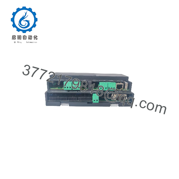
IPG315D
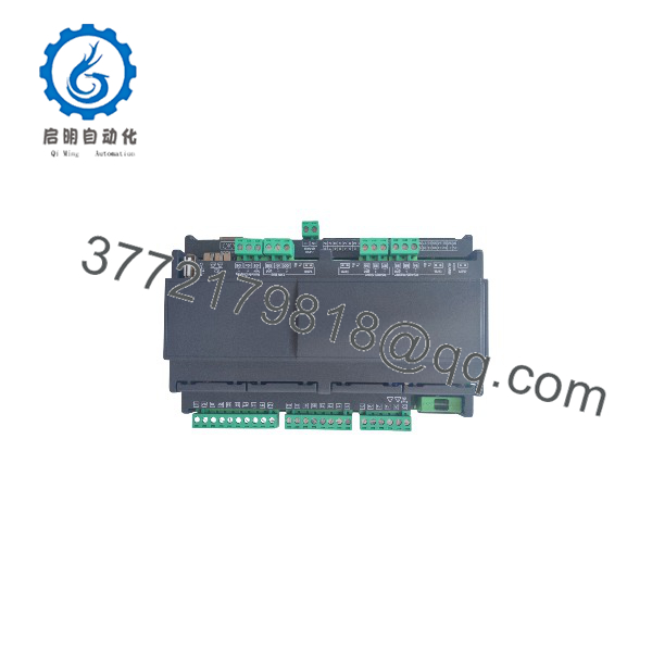
IPG315D
Troubleshooting Quick Reference
| Symptom | Possible Cause | Relevance to This Part | Quick Check Method | Recommendation |
|---|---|---|---|---|
| No LEDs or display activity | Missing supply, incorrect voltage, blown F3AL250V fuse, internal power fault | ✅ High | Measure 24 V AC at the supply terminals or 20–36 V DC at the input; inspect the onboard fuse | Correct supply and fuse issues before replacing the controller |
| Controller repeatedly reboots | Undersized transformer, voltage drop, wiring fault, excessive external load | ⚠️ Medium | Monitor supply voltage while relays and outputs operate; verify the 20 VA AC or 15 W DC requirement | Correct the supply capacity and wiring before condemning the |
| Analog sensor reads open or out of range | Wrong input type, broken probe, incorrect parameter, wiring error | ⚠️ Medium | Measure the sensor resistance or loop current at the input terminals; compare with the configured input type | Check configuration and field wiring before replacing the controller |
| 4–20 mA input reads incorrectly | Wrong range selection, incorrect loop power, excessive resistance, failed transducer | ⚠️ Medium | Measure loop current in series and verify the input is configured for 2–20 mA or 4–20 mA | Confirm transmitter power and scaling before replacing the analog channel |
| Digital input does not change state | Missing external 24 V AC/DC, failed dry contact, incorrect common wiring | ⚠️ Medium | Measure the input voltage directly at the assigned terminals and test the contact with a multimeter | Repair the field circuit or input wiring first |
| Relay output does not energize | Application logic, interlock, failed relay, missing common supply | ⚠️ Medium | Force the output only under an approved test condition and measure continuity across the NO contact | Check logic and load wiring; replace the controller only after proving relay failure |
| Relay chatters or contacts weld | Excessive inrush, inductive load, contact rating exceeded | ✅ High | Measure load current and compare with the 2 A resistive / 1 FLA, 6 LRA motor rating | Add suitable suppression or an interposing relay; do not oversize the direct load |
| SSR output remains active | Leakage current, noise, incorrect wiring, failed SSR channel | ✅ High | Confirm whether the unit is an SSR and measure output voltage with the load disconnected | Do not use SSR outputs to drive contactors or inductive loads directly |
| Ethernet connection fails | Wrong IP address, duplicate address, cable or switch issue | ⚠️ Medium | Connect locally and verify the controller IP; test with a known-good CAT-5 STP cable | Correct network settings and shielding before replacing the controller |
| RS485 devices drop offline | Incorrect polarity, missing termination, address conflict, shield/ground issue | ⚠️ Medium | Check A/B polarity, termination at both ends, node addresses, and cable continuity | Correct the RS485 installation and use the specified cable type |
| Application was lost after service | Incorrect update procedure, damaged flash memory, wrong BIOS/application file | ✅ High | Check the application and BIOS versions; inspect the USB update structure and event history | Restore only with the correct Dixell files; disconnect loads during updates |
| Clock or RTC alarms appear after storage | Internal battery discharged | ❌ Low | Leave the unit powered and synchronize the clock after the battery recharges | Confirm the alarm clears before returning the controller to service |
Support note: Contact technical support with the complete model label, standard or SSR version, wiring photos, application/BIOS version, measured supply voltage, I/O status, and diagnostic logs.
Frequently Asked Questions (FAQ)
What is the Dixell used for?
The is a programmable controller for refrigeration, HVAC, chillers, heat pumps, air-treatment systems, cold rooms, and similar equipment. Its configurable I/O allows one controller platform to be adapted to different machine designs. It is not a safety-rated controller and must not be used as the sole safety device.
What is the difference between and SSR?
The standard uses 15 electromechanical normally open relay outputs. The SSR version provides standard relays on RL1–RL10 and SSR outputs on RL11–RL15. SSR outputs have different electrical behavior and are not designed to drive contactors or inductive loads directly.
Can the accept 4–20 mA signals?
Yes. The 10 configurable analog inputs can accept 2–20 mA or 4–20 mA signals, along with several voltage, temperature, and dry-contact input types. Confirm the parameter configuration and external transmitter power before connecting a live current loop.
Does replacing the erase the application?
The controller stores the program and parameters in permanent flash memory, so a power interruption does not normally erase them. A replacement unit may arrive without the site-specific application, however. Back up the application, parameters, IP address, BIOS version, and I/O configuration before removing the original controller.
Can I program it with a PLC programming package?
The iPro platform uses Dixell’s programming environment, including ISaGRAF for the controller application and VISOPROG for supported graphical interfaces. It is not a drop-in replacement for an Allen-Bradley, Siemens, or standard IEC PLC project without application conversion and commissioning.
Is the still available as a new factory part?
Availability depends on the exact production revision and supplier inventory. Before ordering, request the full product label, date or production code, standard-versus-SSR confirmation, connector set, firmware or BIOS version, warranty, and stock location. “New” should be clarified as factory sealed, unused surplus, or tested refurbished.
What should I verify before replacing one?
Match the complete order code, output version, connector style, application, and communication configuration. Record every terminal wire, input type, relay common arrangement, Ethernet address, polarity, CANbus termination, and controller file before removal. Do not power the unit until the 24 V AC/DC supply and all load wiring have been checked.



