
 WhatsApp: +86 16626708626
 Email:
  Phone: +86 16626708626
Description
Key Technical Specifications
| Parameter | Value |
|---|---|
| Manufacturer | Duplomatic Automation |
| Model | DDC4-10-400/20 |
| Alternate Formatting | DDC4-10-40020 |
| Product Type | CNC turret servo controller / brushless motor drive |
| Application | Duplomatic SM*, TRM-S, and FL-series CNC tool turrets |
| Main Power Supply | 3-phase 400 V AC |
| Main Supply Tolerance | +15% / −10% |
| Mains Frequency | 50/60 Hz |
| Rated Motor Output Current | 10 A maximum |
| Auxiliary Control Supply | 24 V DC ±10% |
| Auxiliary Supply Demand | 35 W reported |
| I/O and Electrovalve Supply | 24 V DC ±10%; up to 5 A reported |
| Feedback System | Resolver-based position feedback; configuration is model/revision dependent |
| Communication Interface | RS-232 diagnostic and PC remote-control interface |
| Configuration Tool | DDC4SW diagnostic and parameter software reported |
| Functions | Tool indexing, turret positioning, reference search, direction selection, inertia selection, and speed-mode control |
| Compatible Turret Types | SM*, TRM-S, and FL turret systems |
| Environmental Protection | IP20; cabinet installation required |
| Reported Operating Temperature | 0 to +55 °C |
| Firmware Dependency | Confirm DSP firmware and I/O firmware before replacement |
| Hardware Revision Dependency | Verify part and revision code, including 0496305 variants where shown on the existing unit |
Duplomatic documentation identifies DDC4-10-400/20 as a rack-model turret control unit for SM*, TRM-S, and FL turrets. It uses a 400 V AC three-phase supply and separate 24 V DC supplies for auxiliary control and electrovalves/I/O. The installation-manual listing specifies 10 A maximum for the DDC4-10-400 model, 24 V DC ±10%/35 W auxiliary input, and 24 V DC ±10%/5 A maximum I/O supply.
Product Introduction
Duplomatic DDC4-10-400/20 is a dedicated digital servo control unit for CNC lathe and machining-center tool turrets. It drives compatible Duplomatic brushless turret motors, manages indexing and position feedback, performs reference search, and exchanges discrete commands and status signals with the CNC control.
This is a turret-specific 400 V, 10 A controller—not a universal servo amplifier. Correct replacement requires matching the turret family, motor, resolver feedback arrangement, tool-count configuration, firmware, 0496305 hardware revision, and stored drive parameters.
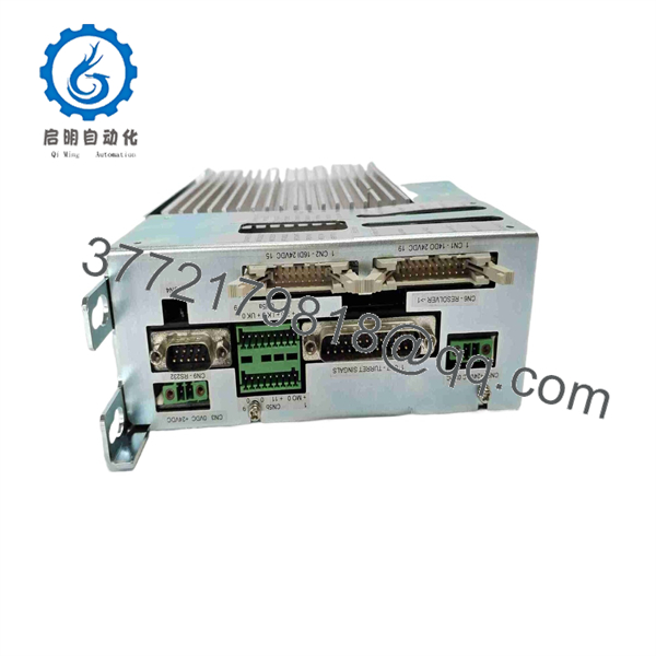
DDC4-10-400/20
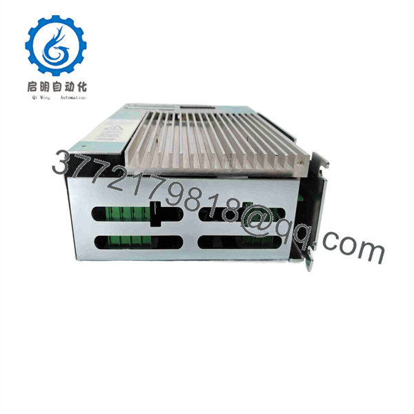
DDC4-10-400/20
Troubleshooting Quick Reference
| Symptom | Possible Cause | Relevance to This Part | Quick Check Method | Recommendation |
|---|---|---|---|---|
| Controller display or LEDs remain off | Missing 400 V AC mains, missing 24 V DC auxiliary supply, open upstream fuse, faulty disconnect, loose terminal, or failed controller | ✅ High | With approved electrical PPE and meter, measure all three phase-to-phase voltages at the input terminals. Then measure 24 V DC at the auxiliary-control terminals. | Verify both the three-phase supply and the separate 24 V DC supply before replacing DDC4. |
| Turret will not index | CNC command missing, interlock active, no 24 V DC I/O supply, failed clamp/unclamp solenoid, motor fault, feedback fault, or controller fault | ✅ High | Monitor the CNC tool-change command and the input status. Verify the I/O supply, then measure voltage at the turret clamp/unclamp valve coil during command. | Check machine permissives and valve circuits first. Do not condemn the drive because a hydraulic or pneumatic turret cannot mechanically unclamp. |
| Turret rotates but stops at the wrong tool station | Resolver feedback error, incorrect tool-count setup, lost reference, parameter mismatch, mechanical coupling slip, damaged resolver cable, or drive fault | ✅ High | Run the approved reference or homing routine. Inspect resolver connector seating and cable shielding. Compare configured turret positions/tool count with the installed turret nameplate. | Do not change parameters blindly. Back up existing settings before adjustment; replace the controller only after feedback and mechanical alignment pass inspection. |
| Turret hunts or oscillates around position | Incorrect inertia setting, wrong motor parameters, damaged resolver feedback, mechanical backlash, loose turret coupling, or unstable drive tuning | ✅ Medium | Check for mechanical play with power safely removed. Review inertia and speed settings using approved software or documented selector settings. | Verify mechanics first. A loose coupling or worn indexing mechanism can imitate a servo-tuning fault. |
| Drive trips during indexing | Motor winding short, phase-to-phase fault, jammed turret, excessive inertia, shorted cable, incorrect parameter set, weak mains supply, or failed power stage | ✅ High | Record the fault code before cycling power. Isolate power, then measure motor winding balance and insulation according to OEM procedures. Inspect turret movement mechanically. | Do not reset repeatedly. Identify whether the trip follows the motor/cable/mechanics or remains with the unit. |
| CNC receives no “in-position” confirmation | Incorrect output mapping, 24 V DC I/O supply missing, output fuse fault, wiring issue, position not achieved, or failed digital output | ✅ Medium | Verify actual turret position and compare the output state to the CNC input state. Measure 24 V DC at the output terminal and at the CNC input. | Trace the signal path. A missing confirmation often comes from interface wiring or a CNC input, not the servo controller. |
| RS-232 connection fails | Wrong cable, incorrect COM settings, unsupported laptop adapter, port damage, or software-version mismatch | ❌ Low to Medium | Use the documented serial cable and verify COM port, baud rate, parity, stop bits, and DDC4SW software compatibility. | Try a known-good service cable and laptop before declaring the RS-232 port faulty. |
| Drive operates briefly, then trips when warm | Cabinet overheating, blocked airflow, fan failure, loose high-current terminal, degraded power components, overloaded motor, or thermal protection | ✅ Medium | Inspect cabinet fans and filters. Use thermal imaging under controlled operation and record drive fault history. | Correct cooling and terminal issues. Replace the unit if thermal trips repeat with verified motor load and proper cabinet temperature. |
| Several turret-related faults occur after replacement | Incorrect parameters, wrong firmware, different 0496305 revision, incompatible turret/motor setup, incorrect wiring, or missed resolver configuration | ✅ High | Photograph old and replacement labels, including code, 0496305 suffix, DSP firmware, and I/O firmware. Restore backed-up parameters before enabling machine motion. | Stop commissioning and compare every revision and parameter. A “same model” controller may still be wrong for the turret. |
❗ This controller has two power systems to verify. The 400 V AC three-phase mains powers the drive stage, while separate 24 V DC supplies support the controller and I/O/electrovalve functions. A healthy 400 V input does not prove the turret controller can process commands or operate valves.
❗ Record parameters before removal. Tool count, turret type, motor setup, resolver configuration, inertia selection, speed settings, reference behavior, and firmware all matter. I have seen a replacement drive energize normally, then index the wrong direction because the original parameter set was never saved.
❗ Do not test turret motion with people near the spindle or turret. A wrong index command, lost reference, or unexpected unclamp event can create sudden mechanical movement. Use the machine builder’s approved maintenance mode and keep the work envelope clear.
❗ Resolver wiring is not ordinary I/O wiring. Keep resolver cables shielded and routed away from motor leads. Do not change connector pinouts from memory. Check the turret electrical manual and record the original wiring first.
If you need support, provide photos of the label, 0496305 revision, DSP/I/O firmware, fault code, turret nameplate, motor and resolver labels, input/output LED states, 400 V AC readings, 24 V DC readings, and a saved parameter file if available.
Frequently Asked Questions (FAQ)
What is Duplomatic -10-400/20?
Duplomatic -10-400/20 is a dedicated CNC turret control unit and brushless-motor servo drive for compatible Duplomatic SM*, TRM-S, and FL turret systems. It controls turret motor motion, indexing, position feedback, reference search, and interfaces with the CNC using I/O signals and RS-232 service communication.
Is -10-40020 the saart as /20?
Yes. -10-40020 is a common no-slash formatting of . The slash form appears in Duplomatic documentation and product listings. When purchasing, use the complete code from the nameplate and ask for photos showing any extra suffixes, serial data, firmware, and the 0496305 revision code.
Which turret sms use /20?
Duplomatic idenes the /20 rack model for SM*, TRM-S, and FL turret applications. The exact compatible motor, tool-station count, turret size, resolver type, and parameter set vary by machine design. Match the actual turret nameplate and drive configuration; do not assume every Duplomatic turret uses the same model.
I use /20 on 230 V AC?
No. This model is designated for a 400 V AC three-phase main supply. Do not apply 230 V AC and expect normal drive operation. If your cabinet uses a different supply voltage, confirm whether the machine needs another variant rather than changing transformers or wiring without an engineering review.
Does it need an external 24 V DC supply?
Yes. The cited installation information lists a separate 24 V DC ±10% auxiliary supply, reported at 35 W, plus a separate 24 V DC ±10% I/O/electrovalve supply up to 5 A. Check the exact terminal diagram for your revision before wiring. Do not assume the 24 V control circuits are generated internally by the 400 V drive input.
Can I replace it with any 10 A, 400 V servo drive?
No. A generic servo drive will not be a drop-in replacement. handles turret-specific functions including indexing, reference search, feedback processing, tool-position logic, valve coordination, and CNC interface signals. A generic 10 A drive may spin the motor but will not necessarily operate the mechanical turret safely or communicate correctly with the machine control.
A retrofit is possible only as an engineered redesign that includes motor feedback, PLC/CNC logic, safety circuits, valve control, enclosure changes, programming, and full machine validation.
Will I lose turret settings during a controller replacement?
You can, unless you back them up first. The existing unit may contain or depend on settings for turret configuration, number of stations, motor parameters, feedback orientation, acceleration, inertia range, maintenance speed, reference routine, and interface behavior.
Before removal:
- Save the parameter set using the approved service tool where possible
- Record DSP and I/O firmware versions
- Photograph all nameplates, connectors, terminals, switches, and LED states
- Record the turret model, station count, motor data, and resolver data
- Capture active fault history and CNC alarm text
- Mark every disconnected wire and connector
- Verify whether the replacement uses the same 0496305 revision and firmware generation
Do not rely on default settings. Default parameters can produce wrong-direction movement, wrong indexing, or an uncontrolled turret reference sequence.
Can t-swap /20?
No. Do not hot-swap a three-phase turret servo controller. It has hazardous 400 V AC input, stored DC-bus energy, 24 V DC auxiliary circuits, motor outputs, and machine-motion control connections.
Stop the machine, lock out the incoming three-phase and 24 V DC supplies, wait for stored energy to discharge, verify absence of voltage using an approved meter, and use the machine builder’s maintenance procedure. Then apply ESD precautions before handling the controller.
Why is a New Surplus cheaper than current factory service pricing?
New Surplus inventory may come from machine-builder stock, canceled projects, maintenance stores, distributors, or warehouse liquidation. It may cost less because it is older stock, has no current OEM commissioning support, or is sold outside the original machine-service channel.
For a turret controller, condition labels need proof:
- New Original / New Surplus: Request photos of the actual label, box, terminals, fan vents, seals, and accessories
- Factory Sealed: Request seal, label, and packaging photos
- Refurbished (tested): Request a test record showing power-up, output behavior, I/O checks, communication, and fault-free operation
- Used, untested: Highest risk; avoid for an outage-critical spare
What tests should a supplier perform before shipping?
Request testing on the specific unit being shipped:
- Verify /20 label, 0496305 revision, serial number, and visible firmware information
- Inspect power terminals, motor terminals, I/O connectors, resolver interface, enclosure, and PCB areas for corrosion, heat damage, cracked terminals, or rework marks
- Power up with the correct three-phase 400 V AC supply and independent 24 V DC auxiliary/I/O supplies
- Confirm boot sequence, status LEDs, and fault-free idle state
- Verify RS-232 connection and parameter readout where the test fixture supports it
- Test CNC command inputs and status outputs using an isolated 24 V DC I/O simulator
- Test motor-phase output and resolver feedback only on a compatible test motor or turret fixture
- Run a sustained load test while monitoring current, fault history, and temperature
- Package in ESD-safe material with terminal protection and a dated QC test report
For a turret drive, “powers on” is not a meaningful final test. Ask whether the supplier tested the feedback loop, command I/O, motor output, and sustained operation.



