 WhatsApp: +86 16626708626
 Email:
 Phone: +86 16626708626
Description
Key Technical Specifications
| Parameter | Value |
|---|---|
| Manufacturer | Eaton Crouse-Hinds MTL |
| Model | MTL5544 |
| Product series | MTL5500 |
| Product type | Repeater power supply / galvanic isolator |
| Number of channels | 2 |
| Input signal range | 0–24 mA, including overrange |
| Output signal range | 4–20 mA nominal; 0–24 mA under/overrange |
| Power supply | 20–35 V DC |
| Current consumption | 96 mA at 24 V DC |
| Power dissipation | 1.4 W at 24 V DC |
| Transmitter types | 2-wire or 3-wire |
| Transmitter voltage | 16.5 V at 20 mA |
| HART communication | Supported on specified terminals |
| Transfer accuracy | Better than 15 µA at 20°C |
| Temperature drift | Less than 0.8 µA/°C |
| Response time | Within 10% of final value in 50 µs |
| Output load resistance | 0–360 Ω at 24 mA; 0–450 Ω at 20 mA |
| Output ripple | Less than 50 µA peak-to-peak |
| Galvanic isolation | 250 V RMS between safe-area circuits and power supply |
| Mounting | 35 mm DIN rail |
| Dimensions | 109.8 × 118.8 × 15.8 mm (L × H × W) |
| Weight | 150 g |
| Operating temperature | −20°C to +60°C |
| Storage temperature | −40°C to +80°C |
| Relative humidity | 5–95% |
| Standards and approvals | IECEx/ATEX and IEC-related specifications; verify the applicable certificate and revision |
Source: Eaton’s official MTL5544 product specifications and MTL4500/5500 series documentation.
Product Introduction
The Eaton MTL5544 is a two-channel intrinsically safe repeater power supply in the MTL5500 series. It supplies power to two 2-wire or 3-wire transmitters located in hazardous areas and repeats their 4–20 mA signals to safe-area control equipment. The module also supports bidirectional HART communication through designated terminals, allowing compatible smart transmitters to be configured and interrogated without disconnecting the measurement loop.
The MTL5544 is used in process instrumentation systems where hazardous-area measurements must interface with PLC, DCS, or monitoring equipment. Its two-channel design consolidates two signal interfaces in a narrow DIN-rail module. Before replacement, verify the transmitter wiring, output load, HART connection, and intrinsic-safety requirements for the installed circuit.
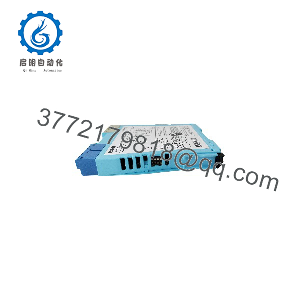
MTL5544
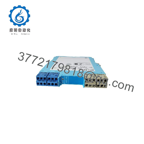
MTL5544
Installation & Configuration Guide
Stage 1: Pre-Installation Preparation
Estimated time: 10–20 minutes
- Confirm the work authorization. Notify operations and establish the approved process safe state. Identify affected control loops, alarms, and any required bypasses.
- Isolate the power supply. Apply the site’s lockout/tagout procedure and verify the circuit is de-energized. Follow the applicable hazardous-area work permit and manufacturer safety instructions.
- Record the existing wiring. Photograph the module label, terminal connections, transmitter wiring, safe-area output wiring, and power connections.
- Verify the replacement. Confirm the full model number is MTL5544, rather than MTL5544S or MTL5544D. These variants must not be assumed interchangeable.
- Prepare the tools. Use an appropriate multimeter, insulated screwdriver, wire labels, terminal tools, and the applicable MTL5500 installation manual.
Stage 2: Remove the Existing Module
Estimated time: 5–10 minutes
- Confirm that the affected instrumentation loops are in the approved maintenance state.
- Label all conductors before disconnecting them.
- Disconnect the transmitter input, safe-area output, and DC power wiring according to the documented terminal assignments.
- Release the DIN-rail retaining mechanism and remove the module without pulling on adjacent conductors.
- Inspect the terminals, rail, and wiring for corrosion, loose connections, or heat damage.
Retain the old module until the replacement has passed functional testing and operations has accepted the restored loops.
Stage 3: Install the MTL5544
Estimated time: 5–15 minutes
- Confirm the replacement’s model number, condition, and applicable intrinsic-safety approvals.
- Mount the module on the 35 mm DIN rail and check that the retaining mechanism is engaged.
- Reconnect the conductors using the manufacturer’s terminal diagram.
| Terminal | Function |
|---|---|
| 1 | Channel 1 current input |
| 2 | Channel 1 transmitter supply positive |
| 3 | Channel 1 common |
| 4 | Channel 2 current input |
| 5 | Channel 2 transmitter supply positive |
| 6 | Channel 2 common |
| 7 | Channel 2 output positive via 220 Ω for HART applications |
| 8 | Channel 2 output negative |
| 9 | Channel 2 output positive |
| 10 | Channel 1 output positive via 220 Ω for HART applications |
| 11 | Channel 1 output negative |
| 12 | Channel 1 output positive |
| 13 | DC supply negative |
| 14 | DC supply positive |
Terminal functions are based on the MTL5544 manufacturer’s datasheet. Verify the applicable revision and the actual wiring diagram before connecting conductors.
- Check that the correct output terminals are used for the intended HART and analog signal arrangement.
- Verify terminal security and maintain the required separation between hazardous-area and safe-area wiring.
Pre-energization checklist
Stage 4: Power-On and Commissioning
Estimated time: 10–30 minutes
- Complete the required electrical and hazardous-area safety checks.
- Restore the 20–35 V DC supply according to the approved commissioning procedure.
- Check the green power LED.
- Verify the output current for both channels against the actual transmitter readings and process conditions.
- Confirm that the receiving PLC or DCS recognizes both measurements and that the readings fall within expected engineering ranges.
- If HART communication is required, test communication using the designated HART terminals and an appropriate communicator or host interface.
- Check alarms, signal scaling, and control-loop response before returning the equipment to service.
Common troubleshooting checks
- No output current: Check the transmitter supply, input wiring, terminal assignments, and field-device condition.
- Incorrect analog reading: Verify transmitter configuration, loop scaling, output load, and DCS/PLC input configuration.
- HART communication failure: Check the designated HART terminals, communicator connection, loop impedance, and compatibility of the connected equipment.
- Both channels fail: Check the shared DC supply and common installation issues before replacing individual transmitters.
Do not perform insulation-resistance or high-potential tests through connected electronic equipment unless the manufacturer explicitly permits them. Intrinsic-safety circuits must be handled according to the applicable installation rules and certificates.
Frequently Asked Questions (FAQ)
Q1. What does the Eaton MTL5544 do?
The MTL5544 powers two hazardous-area 2-wire or 3-wire transmitters and repeats their 4–20 mA signals to safe-area equipment. It also permits HART communication through designated terminals when used with compatible smart transmitters.
Q2. Is the MTL5544 a two-channel or single-channel isolator?
The MTL5544 is a two-channel repeater power supply. Do not confuse it with the MTL5544D, which has a different single-channel, dual-output configuration. Check the complete part number before ordering.
Q3. Can the MTL5544 support HART communication?
Yes. The MTL5544 supports HART communication on designated terminals for compatible transmitters. Correct terminal selection and loop configuration matter; connecting the analog output alone does not guarantee that HART communication will work.
Q4. Can I replace the MTL5544 with an MTL5544S or MTL5544D?
Do not assume these models are direct substitutes. The MTL5544S uses a different safe-area output arrangement, while the MTL5544D is a single-channel dual-output model. Review the transmitter interface, output type, HART requirements, terminal assignments, and safety parameters before choosing an alternative.
Q5. Can the MTL5544 be hot-swapped?
Do not assume live replacement is permitted. Removing the module may interrupt the measurement loop, and hazardous-area work introduces additional restrictions. Follow the site’s isolation procedure, the applicable permit requirements, and the manufacturer’s installation instructions.
Q6. Is the MTL5544 available as new original stock?
Stock availability and condition must be confirmed with the supplier. Ask for photographs of the actual module, the model label, packaging, and any available test documentation. Have the supplier state whether the unit is factory sealed, new surplus, or refurbished and tested. These descriptions are not interchangeable.
Q7. What should I verify before purchasing an MTL5544?
Confirm the exact model number, condition, supply voltage, two-channel wiring arrangement, HART requirements, output load, hazardous-area approval, delivery lead time, and warranty terms. For critical applications, request traceable inspection and functional-test records.