 WhatsApp: +86 16626708626
 Email:
 Phone: +86 16626708626
Description
Key Technical Specifications
| Parameter | Value |
|---|---|
| Model | MTL5549 |
| Manufacturer | Eaton / MTL |
| Product family | MTL5500 Intrinsic Safety Interface Range |
| Function | Safe-area-to-hazardous-area isolating driver for 4–20 mA devices |
| Number of channels | 2 |
| Signal range | 4 to 20 mA |
| Supported communication | HART, bidirectional digital communication |
| Digital signal bandwidth | 500 Hz to 10 kHz |
| Maximum load resistance | 800 Ω at 20 mA (16 V) |
| Minimum load resistance | 90 Ω; short-circuit detection occurs below 50 Ω |
| Output resistance | Greater than 1 MΩ |
| Under-range / over-range capability | 1 mA under-range; 24 mA over-range with load ≤ 520 Ω |
| Line fault detection | Open-circuit and short-circuit detection |
| Transfer accuracy at 20°C | Better than 20 µA |
| Temperature drift | Less than 1.0 µA/°C |
| Signal ripple | Less than 40 µA peak-to-peak |
| Settling time | Within 200 µA of final value within 100 ms |
| Supply voltage | 20 to 35 V DC |
| Maximum current consumption | 70 mA at 24 V DC with 20 mA signal into a 250 Ω load |
| Power dissipation | 1.6 W at 24 V DC with 20 mA signal into a 250 Ω load |
| Intrinsic-safety output per channel | Uo = 28 V; Io = 93 mA; Po = 0.65 W; Um = 253 V rms or DC |
| Hazardous-area location | Zone 0, IIC, T4–T6 when suitably certified; Division 1, Group A |
| Ambient operating temperature | −20 to +60°C |
| Storage temperature | −40 to +80°C |
| Relative humidity | 5% to 95%, non-condensing |
| Mounting | T-section 35 mm DIN rail |
| Functional safety | SIL2 capable as a single device (HFT = 0); SIL3 capable in redundant configurations (HFT = 1) |
| LED indicator | Green power indication |
The standard MTL5549 detects both open circuits and short circuits. The MTL5549Y variant provides open-circuit detection only; confirm the exact suffix before ordering if short-circuit detection is required.
Product Introduction
The Eaton MTL5549 is a two-channel intrinsic-safety isolating driver for 4–20 mA HART valve positioners, I/P converters, and similar hazardous-area loads. It accepts floating 4–20 mA control signals from a safe-area DCS or PLC and drives up to two field devices, with galvanic isolation between the control system and field circuits.
For HART positioners, it passes bidirectional digital communication, allowing configuration and diagnostics from an operator station or handheld communicator. Its line-fault detection identifies both open and short circuits, while SIL2/SIL3 capability supports selected functional-safety applications.
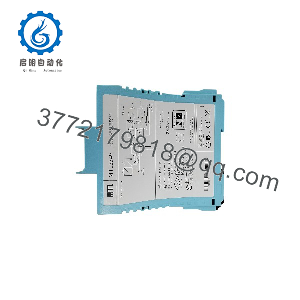
MTL5549
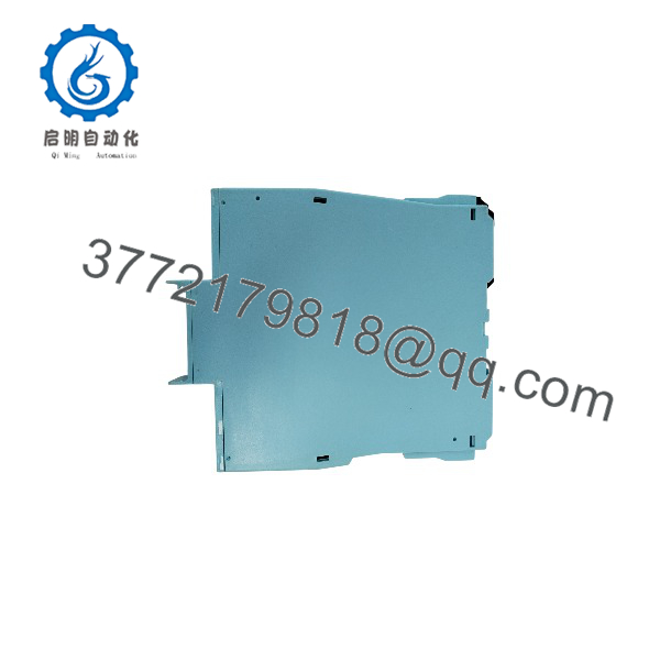
MTL5549
Troubleshooting Quick Reference
| Symptom | Possible Cause | Relevance to this Part | Quick Check Method | Recommendation |
|---|---|---|---|---|
| No output to positioner | Loss of 24 V DC supply, blown fuse, or incorrect wiring | ✅ High | Measure 20–35 V DC at the module supply terminals; inspect DIN-rail seating and fuses | Restore supply or correct wiring before replacing the MTL5549 |
| One channel reads 0 mA | Open field loop or failed I/P converter | ✅ High | Disconnect field wiring and measure loop resistance; check for open circuit at terminals | Repair field wiring or replace the positioner/I-P converter |
| Controller reports open circuit | Field wiring break, loose terminal, or failed positioner coil | ✅ High | With the loop connected, measure input current; open-circuit current is below 0.5 mA on the Y variant and follows the MTL5549 LFD behavior on the standard version | Check field cable continuity and terminal tightness |
| Controller reports short circuit | Shorted field wiring or failed positioner coil | ✅ High | Measure loop resistance; short-circuit detection occurs below 50 Ω on the standard MTL5549 | Locate and repair the short before replacing the isolator |
| Valve does not stroke correctly | Wrong controller scaling, positioner calibration, or mechanical issue | ❌ Low | Command 4, 12, and 20 mA from the DCS and measure actual loop current | Calibrate the positioner; do not replace the isolator first |
| HART communicator cannot reach device | Insufficient loop resistance, wiring issue, or HART configuration problem | ✅ Medium | Verify total loop resistance is within the 90–800 Ω range; check HART connection | Correct loop resistance and check HART device configuration |
| Output unstable or inaccurate | Ground loop, poor shielding, or excessive load | ✅ Medium | Measure loop current with a calibrated mA meter; verify load is ≤ 800 Ω | Correct shielding/grounding or reduce loop load |
| Module LED off | No module power | ✅ High | Confirm green power LED and measure supply voltage | Check power distribution and DIN-rail connection |
❗ Do not assume the MTL5549 has failed because a loop reads low current. A wiring break, failed positioner coil, or loose terminal can look like a dead channel. Check the field loop first.
If the issue remains after checking supply voltage, loop resistance, HART configuration, and field wiring, contact technical support with photos of the module, wiring, and controller diagnostic data.
Frequently Asked Questions
Can I use the Eaton MTL5549 to drive two valve positioners?
Yes. It has two independent channels and is intended to drive two 4–20 mA current-to-pressure converters or other hazardous-area loads up to 800 Ω per channel.
Does the MTL5549 detect both open circuits and short circuits?
Yes. The standard MTL5549 detects both open circuits and short circuits. The MTL5549Y detects open circuits only, so verify the exact suffix if your safety or operations philosophy requires short-circuit detection.
Can I use it with HART valve positioners?
Yes. The module supports bidirectional HART communication over the 4–20 mA loop, so you can configure or interrogate the positioner from the control system or a handheld HART communicator.
Can I hot-swap the MTL5549?
To be honest, this is not a module to pull live without a plan. Although the MTL5500 housing is designed for DIN-rail installation, isolate the relevant loop and follow your plant’s live-work procedure. Removing it under power can disrupt the field loop and may cause unexpected valve movement depending on the positioner’s fail-safe action.
What load can each channel drive?
Each channel can drive up to 800 Ω at 20 mA, equivalent to 16 V across the load. Keep the minimum load at 90 Ω; the standard MTL5549 detects a short circuit below 50 Ω.
Is the MTL5549 suitable for SIL-rated safety functions?
Yes. It has been assessed for IEC 61508 applications and is SIL2 capable as a single device with HFT = 0. SIL3 capability requires a redundant configuration with HFT = 1. Confirm the final SIL calculation against your actual safety requirements and proof-test interval.
Why is New Surplus less expensive than factory-new stock?
New Surplus means genuine Eaton/MTL inventory manufactured earlier but not installed or commissioned. We inspect, document, and functionally verify each unit before shipment. It is not used, repaired, or refurbished stock unless clearly stated on the product page.