
 WhatsApp: +86 16626708626
 Email:
  Phone: +86 16626708626
Description
Key Technical Specifications
| Parameter | Value |
|---|---|
| Manufacturer | Emerson / Westinghouse Ovation |
| Part Number | 1C31132G01 |
| Product Type | Analog Output Personality Module |
| System | Emerson Ovation DCS |
| Channel Count | 4 analog output channels |
| Voltage Output Range | 0–5 VDC |
| Voltage Output Range | 0–10 VDC |
| Current Output Range | 0–20 mA |
| Current Output Range | 4–20 mA configurable |
| Diagnostics | Available with compatible electronic module |
| Associated Electronic Modules | 1C31129G01, 1C31129G02, 1C31129G03, 1C31129G04 |
| Interface | Ovation I/O personality-module / terminal-block interface |
| Approx. Dimensions | 1.0 × 3.3 × 4.8 in |
| Approx. Weight | 0.1 kg / 0.22 lb |
The Ovation I/O Reference Manual specifically lists 1C31132G01 as the personality module for four-channel analog-output configurations. The associated electronic module determines whether the application is 0–5 V, 0–10 V, 0–20 mA, or 4–20 mA, with diagnostic and non-diagnostic variants available.
The physical dimensions and approximately 0.1 kg weight are reported by a secondary-market listing; verify mechanical dimensions against the actual revision before engineering a replacement.
Product Introduction
The Emerson 1C31132G01 is an Ovation DCS Analog Output Personality Module (PMOD) providing the field-interface portion of a four-channel analog output subsystem. It is used with specific Ovation electronic modules to provide 0–5 V, 0–10 V, 0–20 mA, or 4–20 mA output configurations.
The critical point during replacement is the PMOD/EMOD combination. 1C31132G01 alone does not define the complete analog-output function. The installed electronic module, I/O Builder configuration, terminal wiring, and required signal range must all agree.
Installation & Configuration Guide
Stage 1: Pre-Installation Preparation — Approximately 5–10 Minutes
⚠️ Safety First: Notify operations, place the affected control loop in an approved safe state, and follow the site’s LOTO procedure. Do not assume this PMOD can be removed while energized.
Tools Required
- ESD wrist strap
- PH1 screwdriver, where applicable
- Digital multimeter
- Wire labels
- Smartphone/camera
- Approved Ovation I/O documentation
Data Backup
- Record the complete part number: 1C31132G01.
- Photograph the existing PMOD and terminal block.
- Record the I/O slot and channel assignment.
- Photograph every field connection before removal.
- Record the associated electronic module number.
- Record whether each channel is configured for voltage or current output.
- Capture the existing Ovation I/O Builder configuration.
Stage 2: Removing the Old Module — Approximately 5 Minutes
- Place the affected analog loops in their approved maintenance state.
- Remove the applicable cover or retaining hardware.
- Label field wiring by channel.
- Disconnect the terminal wiring carefully.
- Release the PMOD/module retaining mechanism.
- Withdraw the module straight out.
- Inspect the mating connector and terminal interface for bent contacts, contamination, or mechanical damage.
⚠️ Keep the old 1C31132G01 beside the replacement until commissioning is complete. The old module is your best reference for terminal orientation and channel wiring.
Stage 3: Installing the New Module — Approximately 5–10 Minutes
- Verify the replacement is marked 1C31132G01.
- Compare its physical arrangement with the removed module.
- Confirm the associated electronic module is the correct type.
- Connect the ESD wrist strap before handling the module.
- Inspect the connector contacts.
- Install the PMOD in the same position.
- Fully seat and secure the module.
- Reconnect field wiring according to the original photographs and approved wiring diagram.
- Verify polarity and shield connections before energizing.
Self-Checklist
- Part number is 1C31132G01
- Correct EMOD installed
- Correct I/O slot
- Four channel assignments documented
- Voltage/current configuration verified
- Field wiring matches original
- Connector fully seated
- Retaining hardware locked
Stage 4: Power-On & Testing — Approximately 10–15 Minutes
- Inspect the wiring before applying power.
- Check for unintended shorts on the applicable supply and signal circuits.
- Energize the I/O subsystem according to the approved Ovation procedure.
- Confirm normal I/O node communication.
- Open the Ovation diagnostic/I/O configuration tools.
- Verify the correct I/O point assignments.
- Command a controlled output from each required channel.
- Measure the actual output with a calibrated multimeter.
- For current loops, verify the expected 4–20 mA or 0–20 mA behavior.
- For voltage outputs, verify the configured 0–5 VDC or 0–10 VDC range.
- Return the loops to automatic operation after operations approval.
⚠️ Troubleshooting Note: If the controller communicates normally but the field signal is wrong, check the EMOD/PMOD combination first. A 1C31132G01 cannot compensate for an incorrectly selected electronic module or incorrect I/O Builder configuration.
Technical Pitfall & Survival Guide
1. EMOD/PMOD Confusion
❗ This is the biggest trap with 1C31132G01.
The 1C31132G01 is the personality module, while the 1C31129G01–G04 family contains the associated analog-output electronic modules. The Ovation manual explicitly lists these combinations.
I’ve seen replacement orders written simply as “Ovation analog output card.” That is not enough information.
Record both module numbers.
2. Wrong Signal Range
The same 1C31132G01 PMOD can appear in configurations using 0–5 V, 0–10 V, 0–20 mA, and 4–20 mA. The electronic module and software configuration determine the actual signal type.
Do not assume a terminal producing 4–20 mA just because the system uses analog outputs.
3. Terminal Wiring
The Ovation documentation provides specific terminal information for the analog-output PMOD. It identifies signal terminals, references, shield connections, and reserved terminals. Do not wire from memory.
❗ Reserved terminals must remain unused where the documentation specifies them as reserved.
4. Configuration Mismatch
A physically correct PMOD will not fix an incorrect I/O Builder configuration.
Before returning the loop to service, confirm:
- Channel number
- Signal type
- Engineering range
- Diagnostic selection
- Output scaling
- Field-device polarity
5. ESD Damage
Wear a grounded wrist strap and avoid touching connector contacts.
This is an interface module, but that does not make it immune to ESD handling damage. If a replacement fails immediately, inspect installation and handling before assuming the spare is defective.
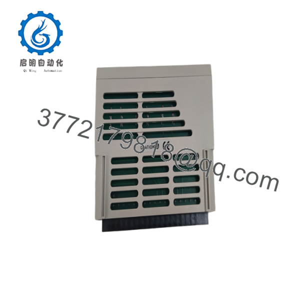
1C31132G01
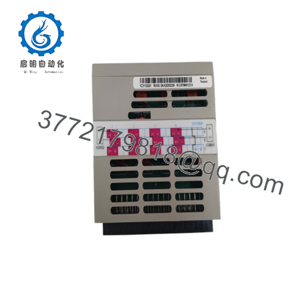
1C31132G01
Frequently Asked Questions (FAQ)
1. What is Emerson 1C31132G01?
The 1C31132G01 is an Ovation Analog Output Personality Module (PMOD). It is used with compatible electronic modules to implement four-channel analog-output configurations.
2. Is 1C31132G01 an analog output electronic module?
No. This distinction matters.
1C31132G01 is the personality module. The Ovation reference documentation pairs it with electronic modules such as 1C31129G01 through 1C31129G04.
If your failed component is marked 1C31129G03, for example, ordering only a 1C31132G01 would not replace the failed electronic module.
3. How many analog channels does 1C31132G01 support?
The documented analog-output subsystem uses four channels with 1C31132G01 as the personality module. Supported configurations include 0–5 V, 0–10 V, 0–20 mA, and 4–20 mA.
4. Can 1C31132G01 be used for 4–20 mA?
Yes, but the complete configuration matters. The Ovation documentation lists a 4-channel 4–20 mA configuration using the appropriate 1C31129G03 electronic module with 1C31132G01. The I/O Builder configuration determines the applicable signal behavior.
5. Is 1C31132G01 obsolete?
It is a legacy Ovation component from the older R3-1150-era I/O architecture. Secondary-market suppliers continue to list it, but availability varies and should not be confused with current OEM production status.
For a planned shutdown, confirm actual physical stock and the exact revision before relying on an online inventory count.
6. Can I hot-swap the 1C31132G01?
Do not assume that it is hot-swappable.
Whether an Ovation I/O component can be replaced online depends on the complete hardware architecture and approved maintenance procedure. If your site documentation does not explicitly authorize live replacement, de-energize the affected hardware under LOTO.
7. Will replacing 1C31132G01 change my control logic?
Replacing the PMOD itself does not normally constitute replacement of the Ovation controller or its application logic. However, the I/O configuration must still be verified after replacement.
Before pulling the old module, document the channel assignments, signal types, scaling, terminal wiring, and associated EMOD. That takes a few minutes and can prevent hours of commissioning work.



