
 WhatsApp: +86 16626708626
 Email:
  Phone: +86 16626708626
Description
Key Technical Specifications
| Parameter | Value |
|---|---|
| Manufacturer | Emerson / Bristol |
| Part Number | 396563-06-6 |
| Product Family | ControlWave Micro |
| Product Type | CPU Module |
| Processor | 32-bit ARM9 |
| Processor Speed | 150 MHz |
| SRAM | 4 MB |
| Flash Memory | 16 MB |
| Program Execution Memory | 4 MB SDRAM |
| Power Requirement | 3.3 VDC |
| Current Consumption | Approximately 240 mA |
| Communication Interfaces | Ethernet, 2 × RS-232, RS-485 |
| Real-Time Clock | Integrated |
| Security | Key-lock security switch |
| Approx. Dimensions | 4.7 × 3.5 × 1.8 in. |
| Approx. Weight | 0.25 lb |
The 150 MHz processor, 4 MB SRAM, 16 MB Flash, integrated real-time clock, and key-lock security switch are documented in ControlWave Micro product information.
Technical verification note: Some reseller listings give different memory descriptions for this part. For a replacement project, verify the actual board revision and the OEM documentation applicable to the installed ControlWave Micro hardware rather than relying on a reseller specification table alone.
Product Introduction
The Emerson 396563-06-6 is a CPU module for the Bristol ControlWave Micro hybrid controller platform. It provides the processor and memory resources required for control execution, data handling, real-time functions, and controller communications. Published specifications identify a 150 MHz ARM9 processor, 4 MB SRAM, and 16 MB Flash.
This is a legacy controller component, so exact revision matching matters more than connector appearance. The part is listed as discontinued by secondary-market documentation, making verified surplus inventory and tested replacement units relevant for maintaining existing ControlWave Micro installations.
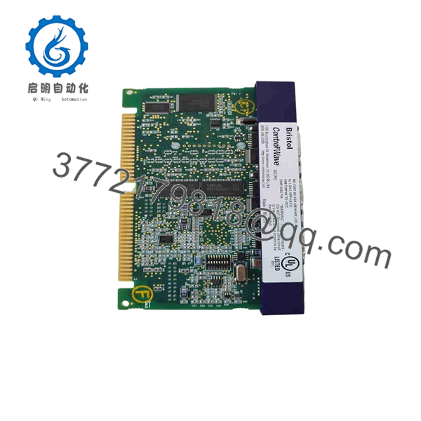
396563-06-6
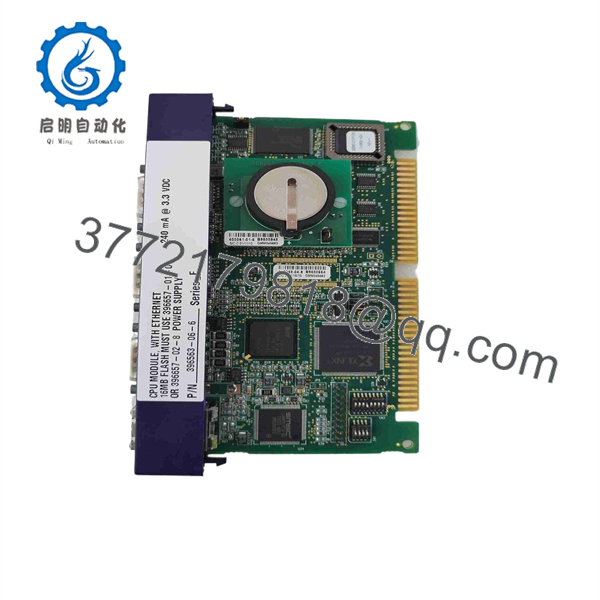
396563-06-6
Installation & Configuration Guide
Stage 1: Pre-Installation Preparation — Approx. 10 Minutes
⚠️ Safety First
- Notify operations and obtain an approved maintenance window.
- Place the controlled process in its defined safe state.
- Apply lockout/tagout (LOTO) to the ControlWave Micro panel.
- Verify the controller supply is de-energized with a properly rated multimeter.
- Wait for stored energy to discharge according to the site procedure.
- Confirm the replacement marking is 396563-06-6 before opening the controller.
Tools Required
- ESD wrist strap
- Appropriate Phillips screwdriver
- Calibrated multimeter
- Wire labels
- Smartphone or camera
- Laptop with the applicable ControlWave engineering software
Data Backup
Before removing the existing CPU:
- Back up the running ControlWave application.
- Record the controller firmware revision.
- Record communication parameters.
- Document Ethernet configuration.
- Record RS-232/RS-485 communication assignments.
- Photograph all board connectors and switch positions.
- Record the existing CPU part number and hardware revision.
⚠️ Do not assume the replacement contains the same application program as the old CPU. A replacement CPU may require application restoration and configuration verification.
Stage 2: Removing the Old CPU Module — Approx. 5 Minutes
- Verify the controller is electrically safe.
- Remove the enclosure or controller cover as required.
- Photograph the complete CPU installation.
- Label connected communication and power wiring.
- Disconnect connectors without pulling on the cable.
- Release the CPU module’s retaining hardware.
- Remove the CPU straight from its mating interface.
- Inspect the connector and backplane for contamination, corrosion, bent contacts, or mechanical damage.
- Keep the old CPU available for comparison until commissioning is complete.
⚠️ Do not use the replacement board’s connector position as the only wiring reference. Confirm each connection against the applicable ControlWave Micro documentation.
Stage 3: Installing the 396563-06-6 — Approx. 5–10 Minutes
- Verify the exact part number: 396563-06-6.
- Compare the replacement CPU with the removed unit.
- Check the hardware revision and visible component layout.
- Put on the grounded ESD wrist strap.
- Verify connector alignment before insertion.
- Insert the CPU without forcing the connector.
- Secure the retaining hardware.
- Reconnect communication and power connections.
- Check that connectors are fully seated.
- Verify that no cable is pinched against the enclosure.
Configuration Checklist
- Part number matches 396563-06-6
- Hardware revision documented
- Firmware revision documented
- Ethernet configuration recorded
- Serial-port assignments recorded
- Connectors fully seated
- ESD precautions maintained
- Application backup available
Stage 4: Power-On & Testing — Approx. 10–15 Minutes
- Perform a final wiring inspection before applying power.
- Verify supply voltage with the multimeter.
- Energize the controller according to the approved procedure.
- Observe the CPU startup sequence and status indicators.
- Connect the engineering workstation.
- Verify the CPU hardware is recognized.
- Check the installed firmware revision.
- Restore the backed-up application if required.
- Verify Ethernet and serial communication parameters.
- Establish communications with connected field devices.
- Check controller diagnostics for active faults.
- Execute a controlled I/O and communication test before returning the process to normal operation.
⚠️ If the replacement CPU powers up but the application does not execute correctly, stop changing hardware. First compare firmware, application revision, memory configuration, communication parameters, and controller configuration with the original unit.
Frequently Asked Questions (FAQ)
Q1. What is Emerson 396563-06-6?
396563-06-6 is a ControlWave Micro CPU module manufactured for the Bristol/Emerson ControlWave Micro controller platform. Available technical references identify it as a 150 MHz CPU with onboard memory and industrial communication interfaces.
Q2. Is 396563-06-6 a DeltaV module?
No. It is associated with Bristol ControlWave Micro, not a standard DeltaV I/O card. Some distributors categorize Emerson products under “DeltaV” because Emerson owns multiple process-control product families. For procurement, identify the installed controller as ControlWave Micro and verify the complete part number.
Q3. Is 396563-06-6 obsolete?
Available secondary-market documentation lists 396563-06-6 as discontinued by the manufacturer. That means procurement should be handled as a legacy-spares requirement rather than assuming normal current-production availability.
Q4. Will replacing the CPU erase my ControlWave application?
The safest assumption is yes, unless you have verified that the application and required configuration are retained elsewhere. Back up the existing application before removing the CPU. After replacement, verify firmware compatibility and restore the application using the applicable ControlWave engineering procedure.
Q5. What processor and memory does 396563-06-6 use?
Available technical references identify a 32-bit ARM9 processor at 150 MHz, 4 MB SRAM, 16 MB Flash, and approximately 4 MB SDRAM for program execution.
Q6. What communication interfaces are associated with this CPU?
Published secondary documentation identifies Ethernet, two RS-232 interfaces, and RS-485. The exact communication configuration depends on the ControlWave Micro hardware and application configuration, so verify the installed revision before assuming every interface is configured identically.
Q7. What condition should I specify when buying a replacement?
Specify the condition explicitly: Factory Sealed, New Original/New Surplus, or Refurbished (tested). Because 396563-06-6 is a discontinued part, ask for photographs of the actual CPU label, hardware revision, packaging, and any available functional-test report. Current listings show that both unused and refurbished units can appear on the secondary market.



