
 WhatsApp: +86 16626708626
 Email:
  Phone: +86 16626708626
Description
Key Technical Specifications
| Parameter | Value |
|---|---|
| Manufacturer | Emerson |
| Platform | Ovation Distributed Control System |
| Part Number | 5X00070G04 |
| Product Classification | Analog Input Module / EMOD Assembly |
| Channel Count | 8 analog input channels |
| Signal Category | Low-level millivolt analog signals |
| Configured Input Ranges | 20 mV, 50 mV, or 100 mV |
| Resolution | 14-bit |
| Sampling Classification | Medium/high speed |
| Installation | Plugs into a compatible Ovation I/O base or carrier assembly |
| System Application | Temperature, low-level transmitter, and millivolt process-signal acquisition |
| Lifecycle Status | Legacy/discontinued-market spare; verify current OEM support status before a major expansion or migration decision |
| Associated Hardware | Confirm the required Ovation personality module, I/O carrier, and terminal assembly against the installed cabinet documentation |
The 5X00070G04 is identified by multiple spare-parts references as an Emerson Ovation eight-channel, 14-bit analog input module with 20 mV, 50 mV, and 100 mV ranges. Market sources also identify it as a discontinued Ovation module, which makes installed-base spares planning more important than routine replenishment.
Product Introduction & Supply Chain Strategy
The Emerson 5X00070G04 is an Ovation analog input electronics module that brings eight low-level millivolt process signals into an Ovation DCS. Typical applications include thermocouple-related signal acquisition and other low-level analog measurements where the existing Ovation hardware configuration requires this exact module and range capability.
This product is a Brand New Surplus unit. It is not used, not pulled from a decommissioned plant, and not refurbished. All modules undergo rigorous quality verification to ensure OEM-level reliability. For an obsolete Ovation installation, a verified New Surplus spare reduces exposure to EOL stock-outs and avoids the Total Cost of Ownership (TCO) risk of an unplanned trip caused by uncertain-condition inventory. A practical policy is one on-site unit for a single critical cabinet, or two units where the module supports generation, boiler, turbine, burner-management, or high-consequence temperature monitoring.
New Surplus means original OEM manufacture, no wear on backplane contacts, no soldered repairs, and original protective packaging where available. Incoming inventory should include serial-number capture, packaging inspection, connector-pin inspection, an ESD-controlled power-up or test-rack check where feasible, and final QC documentation before release to site stock.
Do not base a critical-spares decision on purchase price alone. A lower-cost uncertain-condition module can create a much larger loss if it fails during startup or forces an emergency shutdown. For a legacy DCS module, the cost of one stock-out can exceed the carrying cost of a controlled buffer stock by a wide margin.
Recommended stocking policy
| Installed Base | Criticality | Recommended On-Site Min/Max | Replenishment Approach |
|---|---|---|---|
| 1–4 installed modules | High | Min 1 / Max 2 | Keep one immediately deployable spare; secure a second through cross-site sharing or a qualified supplier |
| 5–15 installed modules | High | Min 2 / Max 3 | Hold two site spares and review supplier availability every quarter |
| More than 15 installed modules | High | Min 3 / Max 5 | Establish frame coverage, document interchangeability, and maintain distributed buffer stock |
| Noncritical application | Moderate/low | Min 0 / Max 1 | Use a regional shared spare or vendor-managed stock where lead time is acceptable |
Treat the 5X00070G04 as an A-class criticality item if a failure interrupts a turbine, boiler, process unit, safety-relevant temperature measurement, or major production train. Because it is legacy inventory, do not rely on normal JIT purchasing. Lead time variability can become extreme when remaining global stock is limited. Use vendor consolidation with qualified sources, maintain emergency escalation contacts, and consider a planned last-time-buy after confirming the actual installed quantity and annual failure history.
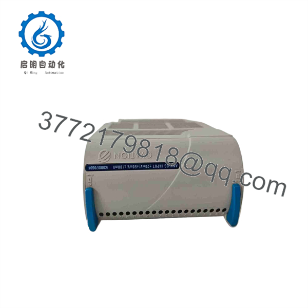
5X00070G04
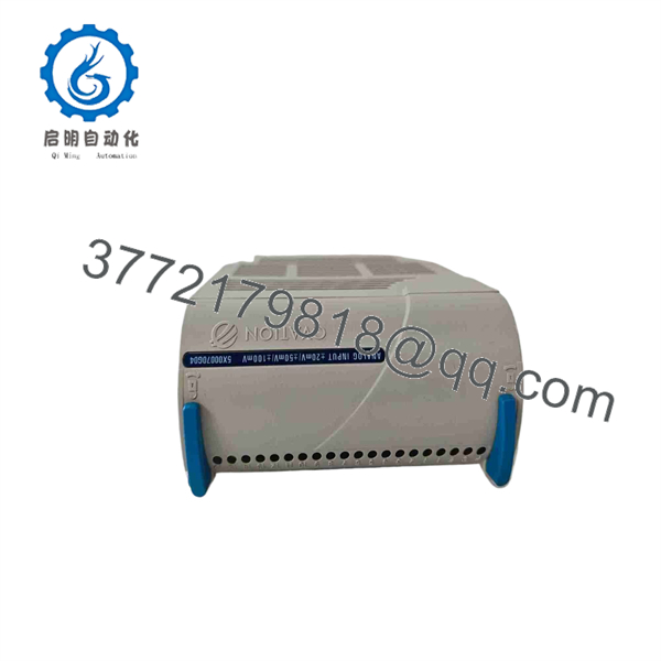
5X00070G04
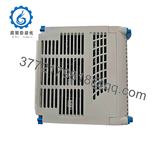
5X00070G04
Installation & Configuration Guide
Stage 1: Pre-Installation (Prep & Safety)
- Confirm the complete part number on the installed module label: 5X00070G04. Do not substitute a different Ovation analog-input model based only on similar appearance or channel count.
- Review the approved Ovation cabinet drawings, loop sheets, module configuration, and current controller diagnostics before touching the hardware.
- Place the affected process loops in a safe operating condition. Coordinate with operations, instrumentation, process control, and safety personnel before removal.
- Apply lock-out/tag-out where the cabinet and site procedure require it. If the system design permits energized service, follow the plant’s approved online-maintenance procedure rather than assuming hot replacement is safe.
- Wear a grounded ESD wrist strap and use ESD-safe handling practices. Prepare the replacement module in an ESD-controlled area.
- Photograph the installed module, carrier, terminal assembly, DIP switches, jumpers, labeling, wiring, status LEDs, and adjacent module positions. Record all settings in the maintenance work order.
- Verify the signal type and expected range for every affected channel. The 5X00070G04 handles low-level analog millivolt inputs; do not connect RTD, 4–20 mA, or voltage signals unless the installed Ovation documentation explicitly specifies the required companion hardware and wiring.
- Inspect the cabinet 24 V DC supply condition and capacity. Confirm the power supply retains at least a 20% operating margin after module replacement.
Stage 2: Removal
- Confirm that operations has accepted the expected loss, manual control action, bypass, or forced-value strategy for the affected signals.
- If required by the approved procedure, isolate cabinet power or the relevant I/O section before removal.
- Release the module retaining mechanism carefully. Do not pry against the I/O base, backplane, or adjacent modules.
- Pull the module straight out along its guide rails. Use even pressure and avoid side-to-side twisting, which can damage connectors or bend mating pins.
- Inspect the removed module’s connector area and the mating base for corrosion, contamination, loose hardware, heat discoloration, or bent contacts.
- Do not transfer configuration assumptions from the old module without verification. Compare its switches, labels, revision data, and associated personality hardware with the replacement plan.
Stage 3: Installation (Clone & Seat)
- Set any configurable DIP switches or jumpers on the New Surplus 5X00070G04 to exactly match the documented settings of the removed unit.
- Confirm that the correct associated Ovation carrier, terminal assembly, and personality module remain installed. A correct electronics module cannot compensate for an incompatible I/O assembly.
- Align the module with the guide rails and insert it straight into the base. Do not force it.
- Apply steady pressure until the module fully seats and the retaining mechanism engages. Verify that the module face aligns evenly with adjacent cards.
- Recheck terminal wiring against marked field wires and cabinet drawings. Do not wire from memory; legacy revisions can differ in terminal assignments.
- Remove tools, loose hardware, packaging, and conductive debris from the cabinet before energizing.
Stage 4: Power-On & Testing
- Before restoring full service, check the 24 V DC rail for abnormal resistance-to-ground or evidence of a short circuit according to site procedure.
- Restore power or return the I/O section to service under the approved operating plan.
- Observe module and controller diagnostics. A normal RUN or healthy indication does not prove correct signal scaling, so also confirm that no ERR, COMM, I/O, or channel-fault indication remains active.
- Review Ovation diagnostics for module recognition, channel health, communication status, and configuration mismatch messages.
- Compare each channel’s displayed value with the known process condition, handheld calibrator, simulator, or field transmitter reference.
- Verify alarming, bad-quality status, scaling, engineering units, and control logic response before releasing loops back to automatic operation.
- Update the maintenance record with the replacement serial number, module revision, configuration evidence, test result, date, and technician approval.
Firmware/Software Versions & Upgrade Notes
- Recommended firmware version: Use the same firmware and hardware revision as the removed 5X00070G04 whenever possible. If an exact revision match is unavailable, obtain Emerson Ovation compatibility confirmation for the installed controller, I/O subsystem, and engineering database before installation.
- Primary compatibility rule: Do not assume that the suffix and physical form factor alone guarantee equivalent behavior. Confirm the 5X00070G04 part number, installed system release, I/O base, personality module, channel range configuration, and controller database definition.
- Backward compatibility risk: A later module revision may initialize differently or report diagnostics that an older Ovation controller or engineering workstation release does not interpret correctly.
- Forward compatibility risk: An older module may not support assumptions made by a later Ovation configuration database, especially where channel diagnostics, calibration data, or I/O scanning behavior changed across system revisions.
- Upgrade warning: Do not upgrade controller, I/O, or associated firmware during an emergency hardware replacement unless the plant has an approved outage plan, verified rollback procedure, complete backups, and vendor-confirmed compatibility. A firmware change introduces variables unrelated to the failed hardware and can turn a one-card replacement into a broader restart issue.
- Downgrade warning: Downgrading can remove support for database features or diagnostic behavior already in use. Preserve current controller backups, module settings, event logs, and configuration exports before any revision change.
- Configuration backup: Before removal, archive the Ovation configuration, capture current diagnostics, record the module location, and photograph all physical settings. This information shortens recovery time if the replacement reports a configuration fault.
Frequently Asked Questions (FAQ)
Are these really new parts?
Yes. This offering is for New Original / New Surplus inventory only. A New Surplus module is original OEM-manufactured inventory that has not been placed into process service. It should show no wear on backplane contacts, no soldered repairs, and no signs of field installation. Quality control should document physical condition, serial information, packaging condition, and functional verification where test capability is available.
Why does New Surplus cost less than OEM new but more than lower-priced market inventory?
OEM list pricing includes current factory support structures, standard channels, and current-production economics. New Surplus pricing reflects the cost of locating, securing, verifying, storing, and warranty-backing genuine legacy inventory. It may cost more than uncertain-condition alternatives because a verified, unused critical spare provides lower downtime exposure and better TCO control.
Is the Emerson 5X00070G04 obsolete or EOL?
Market references identify the 5X00070G04 as a discontinued Ovation module. Treat it as a lifecycle-managed legacy spare: document every installed location, verify remaining qualified supply, establish buffer stock, and prepare a last-time-buy analysis before inventory becomes difficult to source.
What Min/Max quantity should we hold?
For a critical application with one to four installed modules, hold a minimum of one and a maximum of two on-site. For larger installed populations or high-consequence service, hold two to five units based on failure history, vendor lead time variability, cross-site sharing capability, and outage cost. Recalculate annually using actual consumption and current availability rather than a fixed rule.
Can we hot-swap this module?
Do not assume hot swapping is safe simply because the module is installed in an Ovation system. Whether online replacement is permitted depends on the specific I/O architecture, cabinet procedure, process state, signal criticality, and plant operating rules. Place the loop in a controlled state, follow approved procedures, and validate every input after the change.
Will replacing the hardware erase the program or controller logic?
Replacing this analog input module should not erase controller logic, but it can create I/O diagnostics, bad-quality indications, configuration mismatches, or incorrect field values if the module settings, associated hardware, or database definition do not match. Back up the configuration and confirm channel operation before restoring automatic control.
What warranty terms should apply to a New Surplus module?
For critical legacy spares, require a written warranty that clearly identifies the part number, serial number where available, condition classification, functional coverage, warranty duration, return procedure, and replacement or credit terms. A one- to two-year warranty is a reasonable procurement target for verified New Surplus inventory, subject to supplier terms and the testability of the module.



