
 WhatsApp: +86 16626708626
 Email:
  Phone: +86 16626708626
Description
Key Technical Specifications
| Parameter | Specification |
| Manufacturer | Emerson Automation Solutions (formerly Westinghouse) |
| System Architecture | Ovation Distributed Control System (DCS) |
| Part Number | 5X00106G02 |
| Module Type | Electronics Interface Module |
| Mounting Orientation | Ovation Standard Baseboard Slot |
| Power Consumption | Drawn directly from Ovation backplane 24 V DC bus |
| Diagnostics | Onboard LED status indicators (Power, Comms, Fault) |
| Operating Temperature | 0°C to +60°C (32°F to 140°F) |
| Storage Temperature | -40°C to +85°C (-40°F to 185°F) |
| Relative Humidity | 5% to 95% non-condensing |
| Conformal Coating | Standard industrial environment coating |
Product Introduction
The Emerson Westinghouse 5X00106G02 is a specialized electronics module designed for integration into the Emerson Ovation Distributed Control System (DCS). Serving as a critical interface hardware component, it handles high-integrity signal routing and communication handshakes between field interface units and central controller backplanes.
Engineers specify the 5X00106G02 across thermal power plants, municipal water treatment systems, and continuous process facilities requiring deterministic control cycle times. Built to withstand harsh industrial substation and control room environments, the module delivers long-term operating stability while maintaining full backward compatibility with classic Ovation baseboard infrastructure.
Installation & Configuration Guide
Estimated completion time: 15–20 minutes.
Stage 1: Pre-Installation Preparation
- ⚠️ Safety First: Confirm with process operators that the associated loop or subsystem is transferred to manual or safe state. De-energize cabinet power feeds if working on non-redundant racks.
- Tools Required: Grounded ESD wrist strap, small flat-head screwdriver, #1 Phillips screwdriver, smartphone (for jumper photo verification).
- Data Backup: Ensure the current Ovation station configuration and database are backed up at the Engineer Workstation before swapping hardware.
Stage 2: Removing the Old Module
- Put on a grounded ESD wrist strap connected to the cabinet frame.
- Disconnect any front-facing field cabling or connector headers connected to the module faceplate.
- Loosen the top and bottom captive retaining screws holding the card in the rack.
- Pull the module release lever outward and slide the 5X00106G02 straight out along the guide rails to prevent backplane pin damage.
- ⚠️ Note: Inspect the baseboard connector socket for contamination, dust, or bent pins before inserting the replacement.
Stage 3: Installing the New Module
- Compare the new module label with the old module to ensure identical part number (5X00106G02) and group number.
- Check internal or side-mounted configuration jumpers/DIP switches against the original module; mirror the switch positions exactly.
- Slide the replacement card into the baseboard guide rails until the rear edge connector contacts the backplane.
- Firmly push the faceplate to seat the connectors completely, then latch the retaining mechanism.
- Tighten the top and bottom mounting screws securely.
- Self-Checklist: [ ] Jumpers matched to original, [ ] Board fully seated, [ ] Screws tightened.
Stage 4: Power-On & Testing
- Re-apply power to the module rack segment.
- Observe the boot LED sequence on the front panel:
- Power/Active LED: Green indicates stable logic power and active backplane communication.
- Fault LED: Should illuminate briefly during self-test, then go completely dark.
- Open the Ovation Diagnostic Tool on the engineering workstation and verify that the module slot reports normal hardware status without bus errors.
- ⚠️ Troubleshooting Note: A solid red Fault LED or flashing Comms LED usually indicates an unseated module, mismatched revision jumper, or a node address collision on the internal bus.
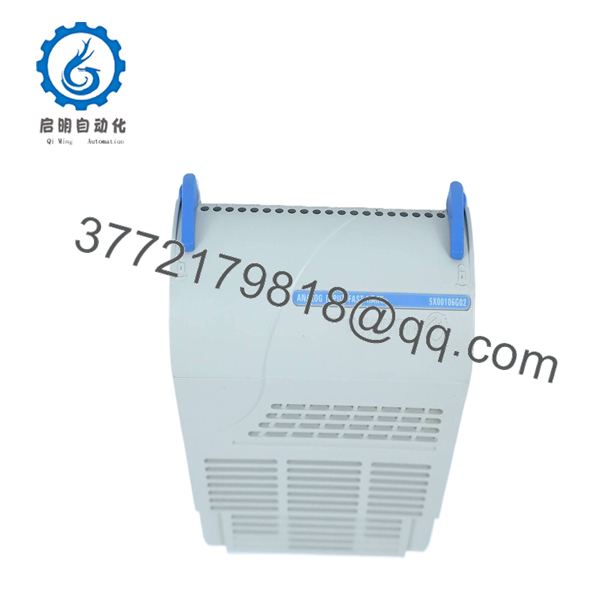
5X00106G02
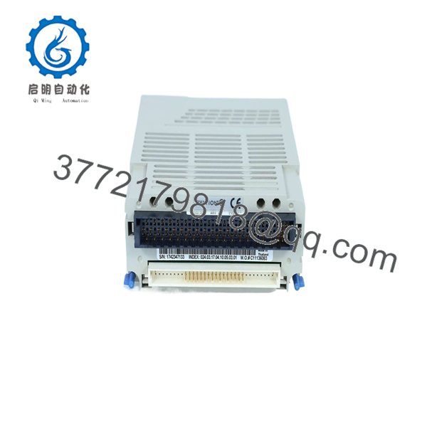
5X00106G02
SOP Quality Transparency
To ensure reliable performance in mission-critical DCS environments, every 5X00106G02 module undergoes a rigorous 5-step quality verification process:
- Inbound Inspection & Traceability:
- Serial number audit against OEM manufacturing databases to confirm genuine Westinghouse/Emerson origin.
- Physical check for component corrosion, PCB stress cracks, burned traces, or socket pin deformation.
- Live Functional Testing:
- Inserted into a live Emerson Ovation test rack containing active controller hardware.
- Power-on self-test validation, communication handshake verification, and signal line continuity checks.
- Minimum 24-hour continuous thermal burn-in under operational load monitoring.
- Electrical Parameter Testing:
- Insulation resistance test using a calibrated Megger instrument at 500 V DC.
- Power rail current draw measurement to ensure the module operates within standard power consumption envelopes.
- Firmware & Hardware Revision Verification:
- Inspection of board revision levels and confirmation of onboard memory/logic integrity.
- Final QC & Packaging:
- Formal sign-off by a quality assurance engineer.
- Unit sealed inside anti-static (ESD) protective packaging, wrapped in shock-absorbing foam, and packaged in heavy-duty shipping containers. Full bench test records are provided upon request.
Technical Pitfall & Survival Guide
- ❗ Jumper and Hardware Switch Misconfiguration:
- Issue: The 5X00106 series boards often feature onboard configuration jumpers for bus addressing or mode selection. Installing a new module with factory-default jumpers can disrupt rack communication.
- Avoidance: Take a clear photo of the DIP switches/jumpers on the old board prior to removal. Set the replacement board’s jumpers to match identically before inserting it into the rack.
- ❗ Incompatible Revision Suffixes:
- Issue: Swapping a G02 revision module with a different group suffix (such as G01 or G03) can lead to subtle backplane signaling errors or firmware incompatibility.
- Avoidance: Ensure the entire part number—specifically the “G02” suffix—matches the original unit in your system schematics.
- ❗ Hot-Swapping Without Verification:
- Issue: Removing the module from a non-redundant slot while live can trigger unexpected trip signals or fatal controller bus faults.
- Avoidance: Verify system redundancy status in the Ovation software prior to pulling the module, or perform the swap during a scheduled maintenance window.
- ❗ Electrostatic Discharge (ESD) Damage:
- Issue: Modern CMOS logic components on Ovation interface boards are sensitive to static discharge. Unprotected handling can cause latent junction degradation.
- Avoidance: Always wear a grounded wrist strap and handle the module strictly by its plastic frame and metal faceplate.
Frequently Asked Questions
Is the Emerson 5X00106G02 hot-swappable in a live system?
Hot-swapping depends on the specific baseboard slot architecture and redundancy configuration. If the slot is part of a redundant, hot-swappable Ovation I/O rack, you can swap the unit under power after taking the loop offline. If the slot is non-redundant, pulling the board live will drop power/communication to adjacent channels and may trip the local controller.
Is the 5X00106G02 obsolete, and what condition are these units in?
Emerson has designated many classic 5X series Ovation components as legacy/limited availability hardware. We supply New Surplus (unused OEM stock in original or protective packaging) and Certified Pre-Owned modules. Every unit is cleaned, bench-tested, and verified on an Ovation test rig.
Do I need to program or flash firmware onto the 5X00106G02 before installation?
In most Ovation architectures, hardware interface cards receive their operating parameters directly from the controller drop upon boot-up. However, you must verify that hardware jumper/DIP switch positions on the board match your original unit so the controller recognizes the module at the correct address.
What warranty comes with this module?
All 5X00106G02 modules supplied by us include a 1-year full replacement warranty. If the module fails under normal operating conditions within 12 months of purchase, we will replace it or issue a full refund.
What should I check if the module does not establish communication upon boot?
First, verify that the module is fully seated and the top/bottom retaining screws are tight. Second, remove the card and double-check that all jumper settings match the original board. Third, check the Ovation station software for slot mismatch alarms or bus address conflicts.



