
 WhatsApp: +86 16626708626
 Email:
  Phone: +86 16626708626
Description
Key Technical Specifications
| Parameter | A6370D Specification |
|---|---|
| Manufacturer | Emerson / EPRO |
| System | AMS 6300 SIS Overspeed Protection System |
| Measurement channels | 1 speed channel per monitor |
| Sensor types | Eddy-current, Hall-effect, magnetic/VR |
| Eddy-current/Hall input | 0–26 V, ±48 V limit range |
| Eddy-current/Hall input resistance | Typically 100 kΩ |
| VR input | 1.0 V peak-to-peak minimum; up to 25 V AC |
| Input frequency | Up to 20 kHz |
| Sensor supply | ±24.5 V ±1.5 VDC |
| Sensor supply current | 35 mA maximum |
| Analog outputs | 2, electrically isolated |
| Analog output range | 0/4–20 mA or 20–4/0 mA |
| Analog output burden | 500 Ω maximum |
| Analog output accuracy | ≤1% of measuring range |
| Binary inputs | 4, electrically isolated |
| Binary outputs | 7, including Channel OK |
| Pulse outputs | 3 isolated open-collector outputs |
| Front TTL output | 0–5 V, up to 20 kHz |
| USB interface | USB 2.0 Type B |
| RS-485 | Up to 32 devices; 38,400 / 57,600 / 115,200 baud |
| System supply | 24 V nominal, +19 to +31.2 VDC |
| Power consumption | 30 W maximum |
| Operating temperature | -20 to +55°C without forced cooling; up to +65°C with forced cooling |
| Storage temperature | -40 to +70°C |
| Relative humidity | 5–95%, non-condensing |
| Protection | IP20 when installed according to the operating manual |
| Dimensions | Approximately 71 mm W × 128 mm H; 3 RU / 14 HP |
| Monitor weight | Approximately 250 g |
| Safety certification | TÜV NORD; capable up to SIL 3 depending on system configuration |
Emerson’s current specification sheet identifies A6370D specifically as the AMS 6300 SIS monitor with one speed channel and a display. The A6370D/DP is the separate version with PROFIBUS functionality, so these two ordering codes should not be treated as interchangeable solely because they share the A6370 designation.
Product Introduction
The Emerson A6370D is a one-channel speed monitor used in the AMS 6300 SIS Overspeed Protection System. It accepts speed signals from compatible eddy-current, Hall-effect, or magnetic/VR sensors and provides speed measurement, limit monitoring, system diagnostics, and protection-related outputs. The monitor is installed with an A6371 system backplane; a complete AMS 6300 SIS normally uses three protection monitors.
For replacement work, the important distinction is that A6370D is safety-related overspeed protection hardware, rather than a general-purpose DCS analog input card. Configuration, sensor type, backplane type, firmware revision, trip logic, and the three-channel protection architecture all need to be checked before commissioning. Emerson’s April 2026 operating manual also documents configuration backup and restoration procedures specifically for monitor replacement.
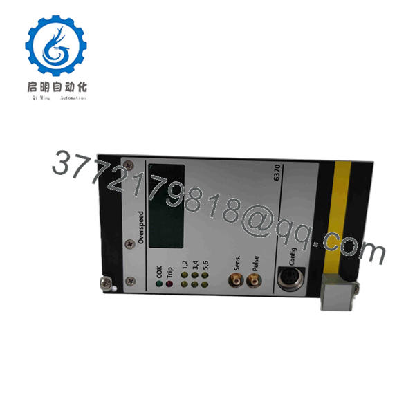
A6370D
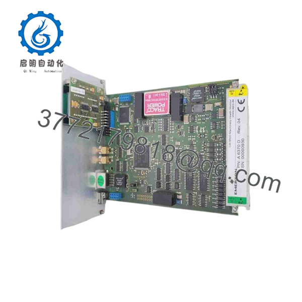
A6370D
Installation & Configuration Guide
Stage 1 — Pre-Installation Preparation
- Place the turbine, compressor, or other protected machine in the required safe operating condition.
- Follow the site’s lockout/tagout (LOTO) procedure and isolate the relevant electrical supply.
- Allow at least 5 minutes for stored electrical energy to discharge before handling the equipment, unless the site/OEM procedure specifies a longer period.
- Record the existing A6370D serial number, firmware revision, bus address, baud rate, backplane type, and configuration.
- If the existing monitor is still accessible, connect a PC through the USB configuration interface and save the monitor configuration file.
- Photograph the existing wiring, terminal assignments, front-panel connections, and jumper positions.
- Confirm that the replacement is , rather than /DP, unless the system was specifically designed for PROFIBUS.
Emerson explicitly instructs technicians replacing a monitor to save the existing configuration, record communication parameters, and retain the old configuration until the replacement has been commissioned.
Stage 2 — Removing the Existing Monitor
- Verify that the overspeed protection system has been placed in the approved maintenance state.
- Disconnect the USB configuration cable and, where applicable, the PROFIBUS cable.
- Remove the monitor’s front mounting screws.
- Release the module carefully from the rack/backplane connector.
- Inspect the F48 connector and mating backplane for contamination, bent contacts, mechanical damage, or evidence of overheating.
- Check the A6371 backplane type:
- A6371/00: Trip Voted
- A6371/10: Trip Not Voted
- Keep the removed available until the replacement has passed functional testing.
Emerson warns that work on the overspeed protection system can impair machine protection. The manufacturer’s replacement procedure also requires attention to the RS-485 jumper configuration.
Stage 3 — Installing the New
- Use appropriate ESD controls when handling the monitor.
- Verify the exact model designation and hardware revision against the existing system documentation.
- Set the RS-485 jumper on the replacement monitor to match the previous monitor.
- Check the selected backplane type in the configuration.
- Insert the into the correct slot and press it firmly but gently into the connector.
- Secure the front mounting screws.
- Reconnect the required field and communication wiring.
- Connect the USB configuration interface to the engineering PC.
- Initialize the replacement monitor if required.
- Load the saved configuration or the approved configuration from the corresponding monitor.
- Restore the bus address and baud rate.
- If PROFIBUS is part of the system, reconnect it only after the monitor configuration has been verified.
The uses a configurable architecture rather than relying on a simple plug-and-play replacement. Emerson’s documented replacement sequence includes copying a saved configuration, restoring communication parameters, and sending the configuration to the new monitor.
Stage 4 — Power-On & Testing
After installation:
- Verify the 24 VDC system supply is within +19 to +31.2 VDC.
- Confirm both redundant supply inputs are correctly wired where applicable.
- Check the front display and Channel OK indication.
- Verify the configured sensor type.
- Confirm that the sensor input signal is present and within the applicable voltage/frequency range.
- Verify the trigger thresholds for eddy-current or Hall-effect sensors.
- Confirm the analog output scaling.
- Check digital input and output behavior.
- Verify the configured trip logic and relay behavior.
- Confirm the three-monitor comparison functions where the complete AMS 6300 SIS is installed.
- Perform the required proof test before returning the protection system to service.
The AMS 6300 SIS provides dedicated proof-test functions for safety-relevant installations. It also continuously supervises analog comparison, pulse comparison, sensor condition, internal temperature, and internal hardware/software status.
A particularly important commissioning check is Channel OK. If the monitor detects a sensor, pulse, analog-comparison, temperature, or internal hardware/software problem, Channel OK can be switched off and the trip output can move to its safe state.
Frequently Asked Questions (FAQ)
1. What is the Emerson used for?
The is a single-channel speed monitor for the AMS 6300 SIS overspeed protection system. It is intended for safety-related rotating-equipment protection rather than ordinary process I/O.
2. Is the same as /DP?
No. Emerson lists as the standard one-channel monitor with display, while adds a PROFIBUS interface. Do not substitute the /DP version or standard version without checking the system design and communication requirements.
3. Which sensors can the accept?
The monitor supports eddy-current measuring chains, Hall-effect sensors, and variable-reluctance/magnetic sensors. The electrical input characteristics differ by sensor type, so the configuration must match the installed measuring chain.
4. Can the be used by itself?
Not as a complete AMS 6300 SIS protection system. The monitor operates with the A6371 system backplane, and the certified system architecture can use three monitors for the protection function. Emerson’s current system packages show three monitors with one A6371 backplane for the standard voted configuration.
5. Does replacing the require reprogramming?
The replacement monitor normally needs its approved configuration loaded. Emerson specifically documents saving the old configuration through USB, installing the replacement, and sending the saved configuration to the new monitor. Bus address and baud rate also need to be restored.
6. Are firmware versions important for replacement?
Yes. Firmware compatibility matters in an AMS 6300 SIS installation. Emerson’s documentation identifies multiple firmware variants and states that mixed firmware operation is subject to defined compatibility conditions; Emerson recommends using the latest supported firmware. Earlier Emerson firmware documentation also warned about incompatibility between specific firmware versions. Verify the complete system revision before replacing only one monitor.
7. What should procurement verify before buying an ?
At minimum, verify the exact model , hardware revision, firmware compatibility, backplane type, sensor type, configuration requirements, communication requirements, physical condition, and serial-number traceability. For a safety-related spare, a visual inspection alone is not sufficient evidence of functional suitability. The replacement should be functionally tested against the approved configuration and system test procedure before being returned to service.



