
 WhatsApp: +86 16626708626
 Email:
  Phone: +86 16626708626
Description
Key Technical Specifications
| Parameter | A6500-UM Specification |
|---|---|
| Manufacturer | Emerson / EPRO |
| System | AMS 6500 ATG Machinery Protection System |
| Measurement channels | 2 |
| Card format | 3U / 1-slot plug-in |
| Rack requirement | A6500-xR System Rack |
| Eddy-current input | -1 to -22 V |
| Eddy-current frequency | 0 to 18,750 Hz |
| Piezoelectric input | +1 to +23 V |
| Piezoelectric frequency | 0 to 18,750 Hz |
| Seismic input | -10 to +15 V |
| Seismic frequency | 0 to 2,000 Hz |
| LF bearing vibration input | -11 to +11 V |
| LF frequency | 0 to 1,000 Hz |
| Hall-effect input | +1 to +22 V; 0 to +30 V for speed measurement |
| VR sensor input | -22 to +22 V; maximum sensor input ±30 V |
| Digital inputs | 5 |
| Key-signal inputs | 2 of the 5 digital inputs |
| Analog outputs | 2 × 0/4–20 mA |
| Analog output accuracy | ±1% of full scale |
| Analog output load | <500 Ω |
| Digital outputs | 6 solid-state relay outputs |
| Digital output load | 100 mA maximum |
| Digital output switching time | <5 ms under specified test conditions |
| Pulse outputs | 2 opto-decoupled collector-emitter outputs |
| Pulse frequency | 0 to 2,000 Hz |
| Raw signal outputs | 1 per sensor input |
| Power consumption | 6 W maximum |
| Operating temperature | -20 to +55°C without forced cooling; -20 to +70°C with forced cooling |
| Storage temperature | -40 to +85°C |
| Relative humidity | 5–95%, non-condensing |
| Protection | IP20 |
| Dimensions | 100 × 160 mm PCB/EURO card format |
| Weight | Approximately 200 g, excluding packaging |
The specifications above are based primarily on Emerson’s A6500-UM specification sheet. In particular, the sensor electrical ranges differ substantially by sensor technology, so a generic statement such as “0–20 kHz universal input” is not sufficient when checking an installed measurement chain.
Product Introduction
The Emerson A6500-UM Universal Measurement Card is a two-channel measurement module for the AMS 6500 ATG machinery protection system. It conditions signals from several common machinery-monitoring sensor types, including eddy-current probes, piezoelectric accelerometers or velocimeters, seismic sensors, low-frequency bearing-vibration sensors, Hall-effect sensors, VR sensors, and LVDT systems used with the A6500-LC.
The important selection point is its configurable measurement architecture. Depending on the sensor and measurement mode, the card can process shaft vibration, case vibration, position, rod gap, rod drop, eccentricity, speed/key signals, and dynamic pressure. The A6500-UM communicates measurement data internally over RS-485 to the -CC communication card, which provides Modbus RTU and Modbus TCP/IP interfaces to higher-level systems.
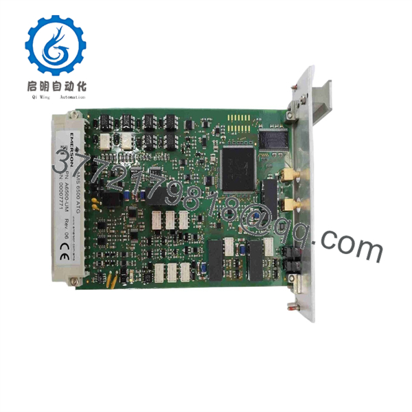
A6500-UM
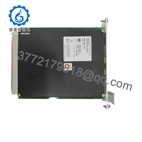
A6500-UM
Installation & Configuration Guide
Stage 1 — Pre-Installation Preparation
Before replacing an -UM:
- Place the protected machinery in the approved maintenance condition.
- Follow the plant LOTO procedure and isolate the applicable electrical supply.
- Allow at least 5 minutes for stored electrical energy to discharge, unless the site procedure requires a longer interval.
- Record the existing card’s model, hardware revision, configuration, and serial number.
- Back up the existing configuration before removing a functioning module.
- Record the sensor type connected to each measurement channel.
- Record the configured measurement function, filtering, scaling, alarm limits, and output assignments.
- Photograph terminal wiring and rack position.
- Verify that the replacement is A6500-UM, not -CC, -RC, or another AMS 6500 module.
he is designed for operation inside an -xR System Rack. Emerson’s current operating manual also states that hazardous-location approval for the measurement card depends on installation in the specified -xR system rack.
Stage 2 — Removing the Existing Module
- Confirm that the machinery protection function has been placed in its approved maintenance state.
- Disconnect or isolate field signals according to the plant procedure.
- Release the front-panel retaining mechanism.
- Carefully withdhe from the rack connector.
- Inspect the backplane connector for bent contacts, contamination, or heat damage.
- Check the card edge connector for oxidation or mechanical damage.
- Retain the removed module until commissioning and functional verification are complete.
Do not treat this as an ordinary PLC I/O swhe can participate directly in machinery protection measurements and limit functions, so incorrect configuration can affect the interpretation of vibration, position, speed, or pressure signals.
Stage 3 — Installing ew
- Use appropriate ESD protection while handling the replacement card.
- Verify the exact model and hardware revision.
- Confirm that the installed rack is an approved -xR rack.
- Check that the measurement configuration matches the sensor technology.
- Insert the card into the correct rack slot without forcing the connector.
- Secure the module according to the rack procedure.
- Restore the field wiring and verify each channel against the recorded wiring documentation.
- Verify the -CC communication-card connection.
- Restore the approved configuration.
- Check alarm limits, filtering, scaling, sensor supply settings, and output assignments.
Pay particular attention to sensor excitatihe uses different electrical interfaces for different sensor types: for example, eddy-current inputs use a negative supply, piezoelectric sensors use adjustable constant-current excitation, and Hall-effect inputs provide a positive sensor supply.
Stage 4 — Power-On & Testing
After installation:
- Verify the rack supply before applying power.
- Confirm the starts without a hardware fault.
- Verify sensor health and cable diagnostics.
- Confirm the actual sensor signal at each channel.
- Check measurement scaling and engineering units.
- Verify the configured measurement mode.
- Test the 0/4–20 mA outputs against the expected measurement values.
- Verify digital input status.
- Verify digital output operation using the approved test procedure.
- Check the raw-signal output where required for troubleshooting.
- Verify RS-485 communication with the -CC.
- Confirm Modbus RTU/TCP data at the host system.
- Perform the required machinery-protection proof test before returning the system to normal service.
he includes self-checking functions for hardware, power input, hardware temperature, sensor, and cable conditions. Its specification also identifies hot-swappable operation and API 670 compliance.
For a replacement module, recommended receiving and commissioning checks should include visual inspection, connector inspection, configuration verification, sensor simulation, analog-output verification, digital I/O testing, communication handshake, and documented functional testing. Do not claim these tests have been completed unless an actual test report exists.
Frequently Asked Questions (FAQ)
1. What is the on used for?
he is the Universal Measurement Card for the AMS 6500 ATG machinery protection system. It processes two sensor channels and supports multiple machinery measurement functions, including shaft vibration, case vibration, position, speed/key, and dynamic pressure.
2. How many measurement channees have?
It has two sensor input channels. The channels can operate independently or be combined depending on the selected measurement mode.
an connect directly to a PLC or DCS over Ethernet?
Not directly through an Ethernet port on the measurement card. Measurement data is transferred internally through RS-485 to the -CC communication card. The -CC then provides Modbus RTU and Modbus TCP/IP communication to host systems.
es support eddy-current probes?
Yes. The eddy-current input supports a -1 to -22 V signal range and a frequency range of 0 to 18,750 Hz. The card also provides the required selectable sensor supply characteristics for the supported measuring chain.
an be used with piezoelectric accelerometers?
Yes. The card supports piezoelectric accelerometer and velocimeter inputs. The specified signal range is +1 to +23 V, with adjustable constant-current excitation from 0 to 8 mA and selectable 2-wire or 4-wire connection.
Is the same e aCC?
No. is the measurement card, while is the communication card. The UM performs sensor measurement and signal processing; the CC transfers measurement information to external systems through the supported communication interfaces.
7.he suitable for safety-related machinery protection?
The Emerson specification identifies the module as API 670 compliant and lists SC 2 / SIL 2 capable under IEC 61508. The actual safety capability depends on the complete certified AMS 6500 system configuration, installation, application, and safety lifecycle documentation; the card should not be treated as an independent SIL-rated protection system.
8. What should be checked before ordering a replnt ?
Verify the exact model, hardware revision, rack type, sensor technology, measurement configuration, firmware/configuration compatibility, and communication architecture. For an installed machinery-protection system, also verify whether the application uses hazardous-area approvals and whether the complete measuring chain remains within the certified installation conditions. Emerson’s documentation lists ATEX, IECEx, CSA, EAC, CCC, PESO, and other approvals for specified configurations.



