
 WhatsApp: +86 16626708626
 Email:
  Phone: +86 16626708626
Description
Key Technical Specifications
| Parameter | Value |
|---|---|
| Manufacturer | Emerson |
| Model Number | CE4005S2B1 |
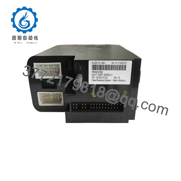
| Associated DeltaV Module | KJ3221X1-BA1 |
| Associated Termination Hardware | KJ4001X1-CA1 |
| Product Family | DeltaV S-Series Traditional I/O |
| Product Type | Eight-channel analog output assembly |
| Output Channel Count | 8 |
| Output Signal | 4–20 mA |
| Digital Communication | HART |
| Channel Protection | Fused eight-channel configuration |
| Typical Field Devices | Valve positioners, I/P converters, VFD analog references, control valves, recorders |
| Mounting Architecture | DeltaV Traditional I/O carrier and matched termination hardware |
| Local Bus Power | 12 V DC, 150 mA reported for the associated assembly listing; verify against the installed hardware label and DeltaV documentation |
| External Field Power | 24 V DC, 300 mA reported for the associated assembly listing; verify against the project power design |
| Reported Channel Power Figure | 24 V DC, 23 mA per channel; application-dependent—confirm using Emerson documentation for the installed configuration |
| Reported Operating Temperature | −40 to +70 °C for the associated assembly listing |
| Reported Dimensions | 107 × 41 × 105 mm |
| Reported Weight | 0.18 kg |
| Replacement Requirement | Match CE4005S2B1, KJ3221X1-BA1, termination hardware, carrier, field wiring, and DeltaV configuration |
Emerson’s DeltaV S-Series Traditional I/O documentation identifies SE4005S2B1 as an eight-channel, fused analog-output configuration for 4–20 mA HART service. Emerson’s M-Series Traditional I/O documentation separately identifies VE4005S2B1 as the standard I/O termination block for an eight-channel 4–20 mA HART analog-output card. Listings that associate CE4005S2B1 with KJ3221X1-BA1 and KJ4001X1-CA1 should therefore be verified against the physical label and original DeltaV bill of materials before purchase.
Product Introduction
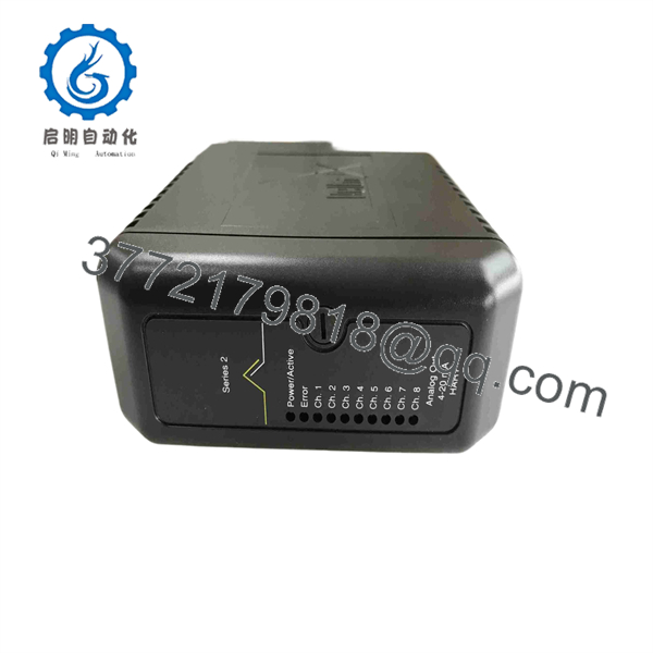
Emerson CE4005S2B1 is an eight-channel DeltaV analog-output assembly used to command field devices with 4–20 mA signals while supporting HART communication. Typical applications include control-valve positioners, I/P transducers, analog references for drives, and other final control elements in a DeltaV process-control system.
This part is selected when a plant needs to maintain an installed DeltaV Traditional I/O architecture with a like-for-like analog-output assembly. The critical checks are the complete hardware stack: CE4005S2B1, the associated KJ3221X1-BA1 component, matched termination hardware, carrier position, field power, and the configured DeltaV channel type.
CE4005S2B1
CE4005S2B1
Troubleshooting Quick Reference
| Symptom | Possible Cause | Relevance to This Part | Quick Check Method | Recommendation |
|---|---|---|---|---|
| No output on all eight channels | Lost DeltaV local bus power, missing 24 V DC field power, unseated assembly, carrier fault, controller or I/O network issue | ✅ High | Check DeltaV diagnostics; measure the applicable local and field power at the carrier/termination points according to site drawings; verify adjacent modules | Check power distribution, carrier seating, and DeltaV diagnostics before replacing CE4005S2B1. |
| One valve remains at 0% or fail position | Open 4–20 mA loop, blown channel fuse, failed positioner/I/P, wiring fault, incorrect channel assignment | ✅ High | Command a known output value from DeltaV; measure loop current at the designated terminal or test point; check the channel fuse with power isolated | Identify whether the current leaves the output channel. Repair field wiring or the final element if current is correct at the terminals. |
| Output reads 20 mA when command is low | Incorrect output action, wrong scaling, wiring polarity error, failed field device, channel hardware fault | ✅ Medium | Compare configured output range and action with the control narrative; measure actual loop current; use a loop calibrator to validate the field device | Correct configuration and field wiring first. Replace the output assembly only if the fault follows the channel after controlled testing. |
| HART communication to a valve positioner fails | HART disabled in configuration, insufficient loop impedance, excessive cable noise, unsupported device settings, field-device fault | ✅ Medium | Review DeltaV device diagnostics; confirm loop current and HART wiring practices; test with an approved HART communicator at the field device | Restore HART configuration and correct the loop before replacing the analog-output assembly. |
| Output is unstable or hunting | PID tuning issue, noisy process signal, poor shield grounding, intermittent field wiring, unstable field power | ❌ Low | Trend controller output, process variable, and actual valve feedback; inspect shield termination; monitor field power during disturbance | Do not replace the output module based on valve movement alone. Prove that the analog output current itself is unstable. |
| Channel shows fault after wiring work | Incorrect terminal placement, damaged termination block, blown fuse, conductor short to ground, field supply fault | ✅ High | Isolate the field loop; inspect wiring against the loop drawing; measure resistance to ground and continuity; inspect the related fuse | Correct wiring and replace the fuse if applicable. Replace only after verifying that no field short remains. |
| Replacement module is recognized but outputs do not match commands | Incorrect module assignment, restored configuration missing, wrong channel mapping, mismatch between card and termination hardware | ✅ High | Confirm module address/location in DeltaV Explorer; compare channel mapping and card type with archived configuration; perform a controlled output stroke test | Restore the correct configuration and validate each channel before returning the loop to automatic control. |
| Assembly runs hot or shows burn marks | Shorted field loop, excessive field load, loose terminals, wrong field power, internal output failure | ✅ High | Isolate power; inspect terminals and fuses; use a clamp meter or loop meter to check current; use thermal imaging during approved loaded testing | Replace visibly heat-damaged hardware, but remove the external short or overload before energizing the replacement. |
❗ Output-action warning: A 4–20 mA output can command a valve toward an unsafe process state if direct/reverse action, fail position, or scaling is wrong. Before putting any loop back in automatic, perform a controlled manual test under the plant’s approved bypass and operating procedure.
❗ Fuse warning: The S-Series documentation identifies the SE4005S2B1 analog-output arrangement as fused. A dead output channel does not automatically mean the electronics failed. Isolate the loop and check the channel fuse, field wiring, and final element before replacing the assembly.
❗ Configuration warning: Do not assume a replacement will inherit its channel mapping. Back up DeltaV configuration, record module location, capture diagnostics, and document every output’s service before removal. A new module in the wrong logical location can drive the wrong field device.
❗ Field-power warning: The output card may look healthy while field power is missing or sagging under load. Measure the 24 V DC field supply at the relevant termination point with the loop commanded active, not only at the power supply terminals.
❗ HART warning: HART issues are often loop issues, not card failures. Check loop resistance, device wiring, shielding, device address, and DeltaV configuration before replacing hardware.
❗ ESD warning: Wear a grounded wrist strap and handle DeltaV electronics by the edges. I have watched a technician solve a wiring issue, then damage a working spare by setting it on a cardboard box in low humidity. Use an ESD mat and strap.
Keep these checks in mind and you will save yourself 90% of typical rework time. If the issue remains unresolved, provide technical support with the full and KJ3221X1-BA1 labels, module location, DeltaV diagnostic screenshots, loop drawings, field-device model, measured loop current, and photos of the termination wiring.
Frequently Asked Questions
What is Emerson ?
Emerson is commonly represented as an eight-channel DeltaV analog-output assembly associated with KJ3221X1-BA1 and KJ4001X1-CA1. It is used for 4–20 mA output loops with HART capability in DeltaV Traditional I/O applications. Emerson’s S-Series documentation identifies the comparable SE4005S2B1 as an eight-channel, fused 4–20 mA HART analog-output configuration.
How many channels does have?
The associated DeltaV analog-output assembly is represented as an eight-channel 4–20 mA HART output configuration. Verify the actual hardware label and system bill of materials before ordering because DeltaV uses related but distinct naming for cards, terminal blocks, and S-Series/M-Series variants.
Does support HART communication?
Yes, the comparable DeltaV S-Series analog-output configuration is documented for 4–20 mA HART service. HART operation still depends on the installed field device, correct channel configuration, suitable loop impedance, cable condition, and the actual card/termination combination in the cabinet.
Can I hot-swap ?
Do not treat it as hot-swappable unless the exact Emerson DeltaV documentation and your plant’s maintenance procedure specifically approve the operation. It controls live analog outputs, so removal can interrupt a loop or cause a final element to move to its configured fail state.
To be honest, pulling an analog-output assembly during a running process without confirming loop status is asking for trouble. Place affected loops in the approved operating state, obtain required operations approval, apply documented bypasses, isolate field circuits as required, and confirm the final element response before removal.
Will replacing erase DeltaV programming?
The field control strategy and database are normally held in the DeltaV control system rather than the analog-output assembly. However, changing the hardware can expose incorrect card assignment, channel mapping, output action, range, HART configuration, or module location.
Before replacement, archive the DeltaV configuration and document:
- Module location and logical assignment
- Every connected final element and loop tag
- Output action, range, and normal operating values
- Current diagnostics and alarm status
- Channel-to-terminal wiring
- Field-device HART settings and device address where applicable
After replacement, stroke-test each affected output in manual mode under approved site procedures before returning any loop to automatic control.
Is the same as VE4005S2B1?
Do not assume they are the same complete item. Emerson’s M-Series Traditional I/O document identifies VE4005S2B1 as a Standard I/O Termination Block for an eight-channel 4–20 mA HART analog-output card, while market listings associate with an analog-output assembly. They may be related within the same DeltaV I/O hardware stack, but they are not automatically interchangeable part numbers.
Order the exact number shown on the removed hardware and verify the associated card, carrier, and termination block.
Why is a New Surplus cheaper than factory supply?
New Surplus units generally come from unused project inventory, cancelled DeltaV expansion work, warehouse spares, distributor stock, or equipment inventories released during plant upgrades. Lower pricing can reflect a secondary supply channel and legacy stock age rather than a defect.
For a New Original / New Surplus item, request:
- Actual photos of the , , and KJ4001X1-CA1 labels
- Confirmation of whether the offer includes the analog-output hardware, termination hardware, or both
- Clear condition statement: Factory Sealed, New Original / New Surplus, or Refurbished (tested)
- Evidence of no corrosion, damaged terminals, broken fuses, rework, burn marks, or altered labels
- Warranty period, return terms, physical quantity, and dispatch lead time
What testing should a supplier complete before shipping?
A supplier should document this test sequence before shipping a analog-output assembly:
- Inbound inspection and traceability: Verify OEM packaging records where available, inspect full labels and associated numbers, check for serial-number alteration, and inspect for scratches, corrosion, rework marks, heat damage, broken terminals, or UV yellowing.
- Mated hardware verification: Install the assembly in a compatible DeltaV Traditional I/O carrier with the correct termination hardware. Confirm mechanical fit, module recognition, and correct position/keying before applying field simulation.
- Live functional testing: Power the test rack from a regulated source, verify startup diagnostics, and command each output across representative points such as 4 mA, 8 mA, 12 mA, 16 mA, and 20 mA. Verify measured output with a calibrated loop meter or Fluke 789 process meter. Confirm channel fault behavior and fused-channel operation where applicable.
- HART communication testing: Connect a compatible HART field-device simulator or known-good HART positioner. Confirm device detection and stable digital communication without corrupting the analog command.
- Load and thermal testing: Run all available channels under representative load for more than 24 hours where test equipment permits. Monitor output stability, card diagnostics, fuse behavior, and enclosure temperature.
- Firmware and configuration verification: Document installed firmware and retain configuration information where applicable. Photograph DIP switches, jumpers, labels, and connector arrangement. A supplier should never claim an unknown configuration is ready for your site.
- Final QC and packaging: Obtain inspector sign-off, place active electronics in anti-static packaging, protect connector pins, use bubble wrap and heavy-duty corrugated boxing, and apply a dated QC-passed label. Test videos, measured results, and photos should be available upon request.



