
 WhatsApp: +86 16626708626
 Email:
  Phone: +86 16626708626
Description
Key Technical Specifications
| Parameter | Specification / Value |
| Manufacturer | Emerson / EZAutomation |
| Model Number | EZ600-TT06S |
| Display Type | 5.7-inch TFT Color Active Matrix LCD |
| Display Resolution | 320 x 240 pixels (QVGA) |
| Touchscreen Type | Analog Resistive Matrix Touch Pad |
| Input Supply Voltage | 24 V DC nominal (20.4–27.6 V DC operating range) |
| Power Consumption | 12 W maximum |
| Serial Interfaces | Port 1: RS-232; Port 2: RS-422/RS-485 (DB15 / terminal block) |
| Supported Protocols | Emerson ControlWave, Modbus RTU/ASCII, Allen-Bradley DF1/DH-485, DirectNET |
| Enclosure Protection | NEMA 4/4X Indoor, IP65 (front bezel when panel-mounted) |
| Operating Temperature | 0°C to +50°C (32°F to 122°F) |
| Backlight Life | 50,000 hours nominal (half-life) |
| Panel Cutout Size | 141 mm x 106 mm (5.55 in x 4.17 in) |
| Unit Weight | 0.85 kg (1.87 lbs) |
Product Introduction
The Emerson EZ600-TT06S is an industrial Human-Machine Interface (HMI) panel engineered for local monitoring and machine control in discrete automation and process environments. Featuring a 5.7-inch TFT color touch screen display, this unit provides operators with real-time process visualization, alarm monitoring, recipe management, and parameter adjustment directly at the equipment enclosure.
Equipped with dual configurable serial communication ports, the EZ600-TT06S interfaces directly with Emerson PLCs, ControlWave RTUs, and third-party controllers running standard industrial protocols such as Modbus RTU. Its NEMA 4X front bezel construction ensures resistance to washdowns and airborne particulates, making it a reliable drop-in replacement during panel retrofits or legacy system upgrades.
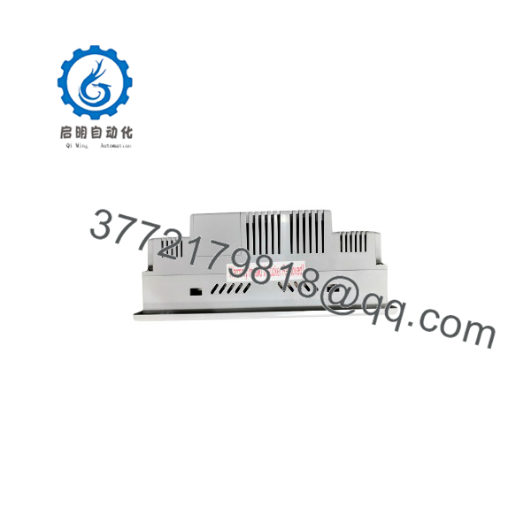
EZ600-TT06S
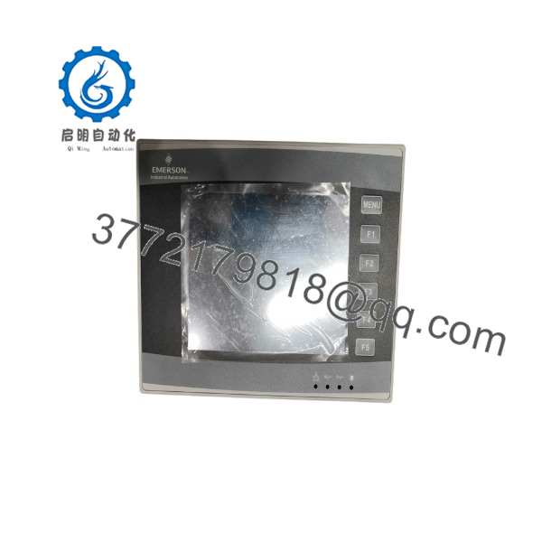
EZ600-TT06S
Installation & Configuration Guide
Stage 1: Pre-Installation Preparation
- ⚠️ Safety First: Notify operations staff of scheduled system maintenance. Isolate and lock out/tag out the 24 V DC power source feeding the control panel. Allow 5 minutes for internal power supply capacitors to fully discharge.
- Tools Required: Grounded ESD wrist strap, PH1 Phillips screwdriver, 2.5 mm slotted screwdriver, wire strippers, digital multimeter (Fluke 115 or equivalent), smartphone or camera for cable tagging reference.
- Data Backup: Upload and back up the existing panel application project (
.EZPfile) via programming software before removing the failed unit. Document PLC driver node addresses, serial port baud rates, and parity settings.
Stage 2: Removing the Old Module
- Open the enclosure door and verify 0 V DC across the power terminals using a multimeter.
- Unplug the 24 V DC power wiring block from the rear of the panel.
- Label and disconnect the serial communication cables (RS-232 / RS-485) attached to Port 1 and Port 2.
- Loosen the rear mounting clamps securing the HMI housing to the panel cut-out.
- Push the panel forward carefully through the front of the enclosure door. Inspect the panel cutout edge and clean away old gasket residue.
Stage 3: Installing the New Module
- Put on a grounded ESD wrist strap. Remove the EZ600-TT06S from its anti-static bag and inspect the housing and glass face for physical damage.
- Verify that the rubber sealing gasket is properly seated in the bezel groove to preserve the NEMA 4X front rating.
- Configuration Clone (Crucial): Set the rear DIP switch bank (if utilizing RS-485 termination or boot mode configuration) to match the original unit’s settings. Ensure termination resistors (120 Ω) are enabled if the unit sits at the end of an RS-485 trunk.
- Insert the EZ600-TT06S into the panel cutout from the front. Secure the unit using the supplied screw clamps tightened uniformly to 0.4 Nm to ensure an even gasket seal.
- Land the 24 V DC supply leads into the power terminal block (+24V, 0V, Frame Ground) and torque screws to 0.5 Nm. Reconnect serial interface cables to their corresponding ports.
Stage 4: Power-On & Testing
- Verify supply voltage polarity at the terminal block before applying main power.
- Apply 24 V DC power. Observe the boot sequence—the screen should illuminate, run internal hardware diagnostics, and load the main runtime application screen.
- Establish communication with the host PLC. Verify that dynamic graphics, alarm banners, and numerical display objects update without “Comms Error” popups.
- Perform a touch calibration test across all four screen corners to confirm resistive matrix responsiveness.
- ⚠️ Troubleshooting Note: If the unit displays a persistent communication timeout error, verify that the serial pinout matches the host controller (specifically RX/TX lines on RS-232 or A/B line polarity on RS-485) and check that the baud rate matches the driver configuration.
SOP Quality Transparency
To guarantee operational readiness and prevent field failures, every Emerson EZ600-TT06S unit undergoes a strict 5-step quality control verification process prior to warehouse dispatch:
- Inbound Inspection & Traceability:
- Documentation verification against OEM shipping records and supply chain origin.
- Serial number auditing and anti-counterfeit checks.
- Visual inspection for bezel scratches, glass cracks, housing oxidation, or terminal post degradation.
- Live Functional Testing:
- Installation into a dedicated test rack powered by a regulated 24 V DC bench supply.
- Power-on self-test verifying bootloader integrity, system RAM, and display backlight function.
- 5-point touch matrix calibration test checking for dead zones or touch drift across the resistive panel surface.
- Serial communication handshake verification (Modbus RTU read/write polling against an Emerson PLC) across all onboard ports.
- Continuous 24-hour thermal burn-in test at ambient load. Official QC Test Report generated upon completion.
- Electrical Parameter Testing:
- Insulation resistance test performed at 500 V DC between 24 V power terminals and chassis frame ground (>10 MΩ threshold).
- Current draw verification under full display brightness (verifying current draw stays within normal limits).
- Firmware & Configuration Verification:
- Firmware version reading and documentation.
- Factory default reset performed to clear previous site configurations while verifying system flash memory.
- Final QC & Packaging:
- Lead QC technician sign-off.
- Sealing inside an ESD anti-static bag with desiccant packets.
- Secure packing using high-density foam inserts within heavy-duty corrugated cartons labeled with QC pass certificates and date codes.
Technical Pitfall & Survival Guide
- ❗ PLC Driver Protocol & Baud Rate Mismatch:
- Issue: The HMI boots up properly, but display tags show static question marks or throw a “PLC No Response” error banner.
- Avoidance: HMI replacement units often revert to factory default port settings (e.g., 9600 baud, 8-N-1). Record the exact communication parameters (baud rate, parity, stop bits, PLC station ID) from the programming software or old panel before installation.
- Field Note: I worked on a plant upgrade where a technician replaced an HMI and spent three hours checking wiring because the screen stayed offline. The issue was simply that the original PLC port was configured for 19200 baud while the replacement panel defaulted to 9600 baud. Match the port properties first.
- ❗ RS-485 Polarity Inversion (A vs. B / + vs. −):
- Issue: RS-485 communication fails entirely even though the wiring appears fully connected.
- Avoidance: Different hardware vendors define RS-485 signal polarities differently (some label Data+ as A, others as B). If your serial communication loop fails to establish, swap the two data lines at the terminal block.
- Field Note: Standard RS-485 differential voltage should show line A slightly more positive than line B during idle states. Keep a multimeter handy to verify line bias voltage if communication drops out.
- ❗ Over-Torquing Panel Mounting Clamps:
- Issue: The touch screen registers phantom touches or becomes unresponsive in specific corners after installation.
- Avoidance: Tighten panel mounting clips hand-tight plus a quarter turn (max 0.4 Nm). Uneven or excessive torque warps the outer plastic bezel, placing constant physical pressure on the resistive touch matrix.
- Field Note: An installer once used a power driver on panel clips during a midnight shift. The bezel warped, holding down the top-right touch contact continuously. The unit appeared broken until we backed off the mounting screws to relieve the physical strain on the glass matrix.
- ❗ Incorrect 24 V DC Power Wiring & Grounding:
- Issue: Screen flickering, touch jitter, or premature backlight failure caused by electrical noise on the 24 V DC bus.
- Avoidance: Run a dedicated 24 V DC power feed directly from a clean industrial power supply. Ensure the HMI frame ground terminal is connected directly to the central panel earth ground bar via a short, thick copper wire.
- Field Note: Avoid tapping the HMI power directly off the same 24 V branch circuit that feeds inductive solenoid valves or large relay coils. Voltage spikes from unsuppressed inductive kicks will corrupt serial communication and reboot the panel display.
Frequently Asked Questions (FAQ)
Can I hot-swap the Emerson while the panel is powered?
No. Always isolate the 24 V DC power supply before removing or landing power and serial terminal connections. Unplugging live terminal connectors on RS-232/RS-485 interfaces can cause transient arcs or ground offsets that risk damaging internal transceiver chips on the circuit board.
What should I do if the original application file is locked or unavailable?
If you cannot upload the runtime file from the old panel, you must compile and download the original project source file using the EZPanel editing software via the serial programming cable. Verify that the runtime driver selected in the software matches the specific PLC model and physical port interface connected in the field.
Is the compatible with non-Emerson PLCs?
Yes. The EZ600 series platform includes embedded serial drivers for multiple PLC brands, including Allen-Bradley (ControlLogix, SLC 500, MicroLogix via DF1 or DH-485), Modicon (Modbus RTU Master/Slave), GE Fanuc, and DirectLOGIC controllers.
What causes a resistive touchscreen to misalign, and can it be recalibrated?
Resistive touch screens can experience spatial drift over time due to thermal expansion, mechanical wear, or long-term UV exposure. You can recalibrate the screen by entering the system setup menu (typically accessed by pressing opposing corners of the screen during initial boot) and running the 5-point touch alignment routine.
How does new surplus inventory compare to factory-new units from the OEM?
New surplus units are unused, original equipment modules sourced from cancelled projects, system integrators, or backup spare inventories. They undergo complete visual, electrical, and live functional load testing before listing to ensure they match original factory operational specifications at a lower cost and shorter lead time.



