WhatsApp: +86 16626708626
 Email:
 Phone: +86 16626708626
Description
Key Technical Specifications
| Parameter | Value |
|---|---|
| Manufacturer | Emerson |
| Model | KJ4001X1-CJ1 |
| Product designation | 32-Channel Terminal Block |
| Voltage rating | 30 V DC |
| Maximum current | 1 A; do not interpret as a per-channel allowance |
| Ambient temperature, November 2021 instruction sheet | −40 to +70 °C |
| Ambient temperature, February 2003 instruction sheet | 0 to 60 °C |
| Shock, November 2021 instruction sheet | 10 g half-sine wave for 11 ms |
| Vibration, November 2021 instruction sheet | 1 mm peak-to-peak, 2–13.2 Hz; 0.7 g, 13.2–150 Hz |
| Relative humidity | 5–95%, noncondensing |
| Airborne contaminants | ISA-S71.04–1985, Class G3 |
| Installation keying | Rotary keys must match the associated I/O card |
Electrical ratings, environmental limits, and keying information come from Emerson instruction sheets. The older sheet also lists different vibration limits. Match the supplied unit’s label and applicable documentation rather than treating every production revision identically.
Warning: The November 2021 sheet prohibits removal or insertion with system power energized. It also states that calibration is unnecessary and the unit contains no user-serviceable parts. ATEX261 and D803007X012 identify documents—not interchangeable hardware ordering numbers.
Product Introduction
The Emerson KJ4001X1-CJ1 is a DeltaV 32-channel terminal block that provides the wiring interface for a compatible I/O card. Its documented electrical rating is 30 V DC with a 1 A maximum current. It is termination hardware, not an analog input card or controller.
Choose it when the existing installation specifies this exact model. Verify rotary key positions, card compatibility, and the supplied unit’s environmental rating before replacement; older and newer Emerson instruction sheets specify different temperature limits.
Troubleshooting Quick Reference
The following checks are diagnostic recommendations, not claims that a particular unit has passed testing. Use the approved assembly wiring diagram; the available instruction sheets do not provide terminal-by-terminal pin assignments. Observe Emerson’s de-energization requirement before removal or insertion.
| Symptom | Possible Cause | Relevance to this Part | Quick Check Method | Recommendation |
|---|---|---|---|---|
| One channel stops responding | Open conductor, loose connection, damaged contact, or I/O channel fault | Possible termination fault; not conclusive | With the circuit isolated, check continuity along the affected wiring path identified in the approved diagram | Repair wiring first; replace the block if a damaged contact or persistent open is confirmed |
| Several channels fail together | Shared supply/common failure, card fault, or connector problem | Possible, but not sufficient evidence of block failure | Review DeltaV diagnostics; check the shared supply and common connections shown in the assembly drawing | Establish whether the fault belongs to the supply, card, cable, or block before ordering |
| Signal changes when the cable moves | Poor connection, broken conductor, or inadequate strain relief | Directly relevant to the wiring interface | After isolation, inspect conductor seating, connector engagement, and cable support | Correct the connection; replace damaged hardware |
| Replacement will not seat | Incorrect rotary key settings or incompatible card/block combination | Directly relevant | Compare the original and replacement key positions with the specified I/O card | Do not force engagement; set keys only according to the approved configuration |
| Terminal damage or discoloration | Excess current, poor connection, or external fault | Direct evidence requiring investigation | Isolate power; inspect contacts and compare connected loads with documented ratings | Correct the initiating fault before installing a replacement |
| Suspected failure without visible damage | Wiring or card configuration issue | Unconfirmed | Preserve diagnostics and compare results using an approved known-good assembly | Request engineering review before replacing parts by trial and error |
If diagnosis remains unclear, contact technical support with label photos, wiring photos, the associated I/O card model, slot location, and diagnostic logs.
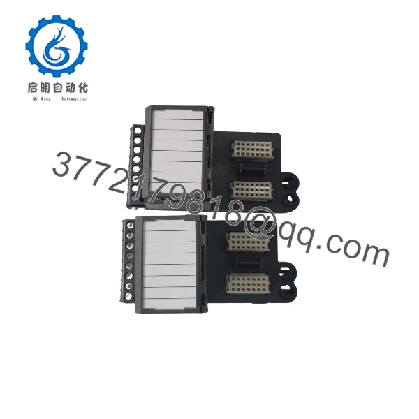
KJ4001X1-CJ1
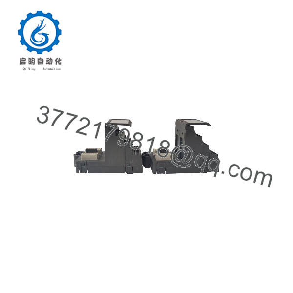
KJ4001X1-CJ1
Frequently Asked Questions (FAQ)
Q1: Can I hot-swap the KJ4001X1-CJ1?
No. Emerson’s November 2021 instruction sheet explicitly prohibits removing or inserting this unit with system power energized. Coordinate the outage with operations and follow the applicable isolation and hazardous-area procedures. Do not assume that redundant I/O permits live terminal-block replacement.
Q2: Is this an analog input module, and will it fit any DeltaV card?
It is a 32-channel terminal block, not an input-processing module. Emerson specifies rotary keying that must match the associated I/O card. A similar appearance or matching channel count does not establish compatibility. Verify the exact card model, key positions, wiring diagram, and assembly requirements before purchase.
The reviewed documentation does not establish universal compatibility with DeltaV S-Series, CHARMs, or Ovation hardware. References to installation manuals alone do not prove interchangeability.
Q3: What should I verify before ordering a direct replacement?
Specify KJ4001X1-CJ1 and provide a readable photo of the original label. Compare hardware identifiers, key positions, connector arrangement, and applicable approvals. Temperature limits need particular attention: Emerson’s February 2003 sheet lists 0 to 60 °C, while the November 2021 sheet lists −40 to +70 °C.
For the associated I/O card, also document firmware, DeltaV version, and configuration. Photograph any actual switches or jumpers; do not assume this terminal block has them.
Q4: Will replacing this block erase my programming?
The documentation identifies it as termination hardware, not a controller or programming-storage device. It does not specify a terminal-block firmware version. Back up the DeltaV configuration before maintenance and preserve wiring and key-setting records; replacement can still interrupt connected signals.
If the scope includes an I/O card replacement, verify that card’s firmware and system compatibility separately.
Q5: Is it obsolete, in stock, or covered by a one-year warranty?
Those claims have not been verified for the seller’s inventory. The reviewed instruction sheets do not establish current lifecycle status, stock quantity, dispatch time, or a seller warranty.
The quotation should state available quantity, actual condition, shipment date, included accessories, warranty duration, return eligibility, and coverage exclusions. Do not publish “limited stock,” “factory sealed,” or “one-year warranty” without supporting records.
Q6: Is New Surplus the same as refurbished, and why might the price differ from an OEM quote?
Keep the condition categories separate. Describe a unit as New Original / New Surplus only when sourcing and inspection records support that description. Identify used, repaired, or refurbished hardware explicitly. Packaging alone does not establish authenticity or unused condition.
No supplied unit, seller price, or provenance record has been reviewed here. A price difference therefore cannot be attributed to surplus sourcing as a verified fact.
Q7: What inspection and test evidence should I request?
Request a unit-specific report using this sequence. This is a proposed acceptance checklist—not a claim that a seller has completed it.
- Inbound inspection and traceability: Match labels to available packing and sourcing records. Inspect for corrosion, connector damage, rework, and plastic discoloration. Audit included accessories and certificates; do not assume holographic tags are present.
- Functional testing: Identify the exact DeltaV carrier, compatible I/O card, configuration, and test equipment. Record assembly startup diagnostics and verify each applicable signal path. If extended testing exceeds 24 hours, report the actual duration, load, temperature observations, and results.
- Electrical checks: Perform isolated continuity and contact checks against the approved diagram. Do not apply a generic 500 V megohmmeter or hipot test: the reviewed sheets provide no such acceptance procedure or limits. Ground-continuity testing requires a documented ground path and approved method.
- Configuration verification: Photograph rotary keys and record associated card firmware and system configuration where applicable. Confirm the test setup matches the intended installation.
- Final QC and packaging: Require inspector sign-off, dated identification, protected connectors, appropriate ESD handling for associated electronics, cushioning, and a suitable shipping carton. Request test photos and videos; advertise their availability only if they exist.
Do not install from memory, force mismatched keys, or bypass isolation. Verify the associated card’s power budget if changing the assembly, and use approved ESD precautions when handling its electronics. These checks provide documented acceptance evidence without inventing field anecdotes or unsupported reliability percentages.