WhatsApp: +86 16626708626
 Email:
 Phone: +86 16626708626
Description
Key Technical Specifications
| Parameter | Value |
|---|---|
| Manufacturer | Emerson / EPRO |
| Model | MMS6312 |
| Ordering number | 9100-00025 |
| Product series | MMS 6000 |
| Measurement channels | 2 independent differential inputs |
| Input resistance | Greater than 100 kΩ |
| Input voltage range | ±27.3 V DC |
| Maximum permissible input voltage | 30 V; confirm polarity and limits in the OEM manual |
| Input frequency range | 0–20 kHz |
| Configurable speed range | Up to 65,535 RPM, depending on configuration |
| Sensor supply | Nominal ±26.75 V DC; 20 mA nominal, 35 mA maximum |
| Power supply | 18–31.2 V DC |
| Power consumption | Maximum 6 W |
| Configuration interface | RS-232 |
| System communication | RS-485 |
| Module dimensions | 30 × 128.4 × 160 mm |
| Net weight | Approximately 320 g |
| Operating temperature | 0 to +65°C |
| Storage temperature | −30 to +85°C |
| Humidity | 5–95%, non-condensing |
| Protection rating | Module IP00; front plate IP21 |
Source: EPRO MMS6312 technical documentation. Actual measurement scaling, alarm behavior, and output configuration depend on the programmed operating mode.
Product Introduction
The EMERSON MMS6312 is a dual-channel speed and key-phase monitor designed for the EPRO MMS 6000 machinery monitoring platform. It processes signals from compatible pulse sensors and eddy-current sensor systems to measure rotational speed, detect standstill, and monitor shaft reference pulses. Its two channels can operate independently or in combined configurations for rotation-direction and differential-speed monitoring.
The module provides configurable measurement ranges, alarm limits, galvanically isolated outputs, and RS-232/RS-485 communication interfaces. These capabilities support machinery monitoring installations where reliable speed feedback and documented alarm behavior are required.
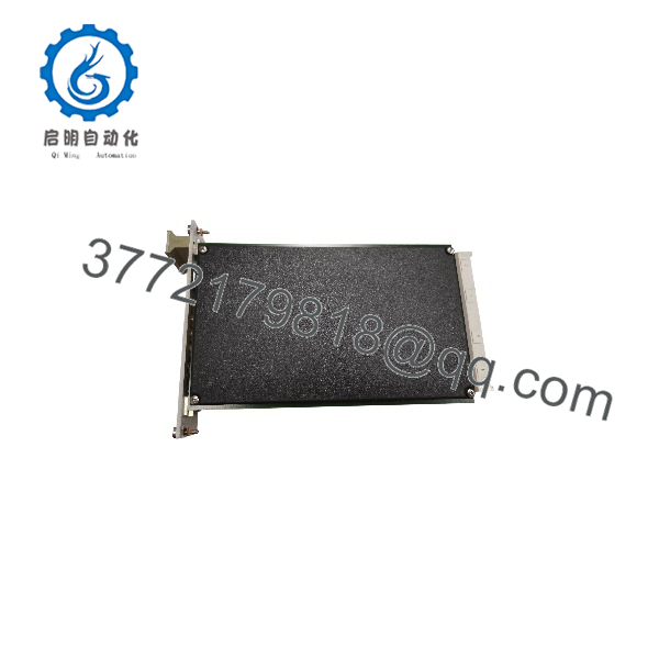
MMS6312
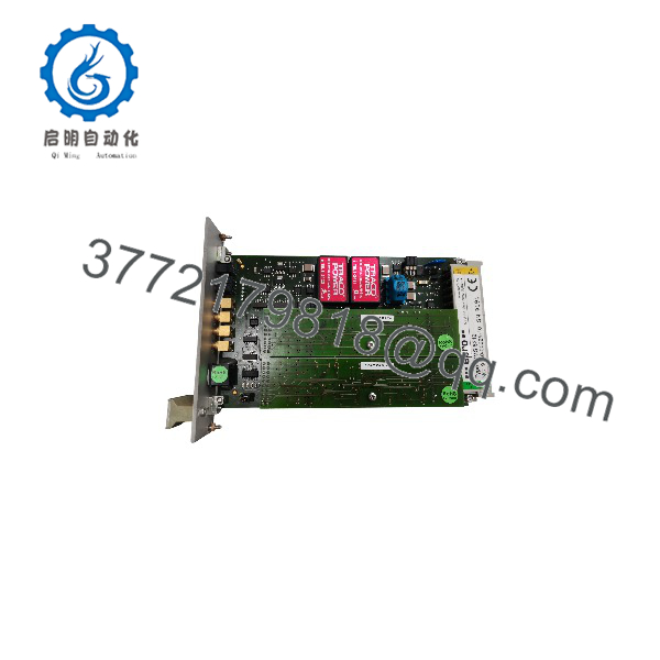
MMS6312
Installation & Configuration Guide
Planning estimate: 20–45 minutes for a straightforward replacement, excluding plant approvals, isolation, and extended functional testing.
Stage 1: Pre-Installation Preparation
- Verify the part number. Confirm MMS6312 and, where applicable, ordering number 9100-00025. Check the installed hardware revision and rack compatibility.
- Coordinate the maintenance window. Obtain operations approval and establish the required machinery protection state.
- Follow site safety procedures. Apply lockout/tagout where required. Do not assume online replacement is safe for every rack or protection configuration.
- Prepare tools. ESD wrist strap, suitable screwdriver, multimeter, wire labels, and camera.
- Back up configuration records. Save accessible settings and photograph the original wiring, channel assignments, and alarm thresholds.
Stage 2: Remove the Existing Module
- Confirm the approved isolation or online-replacement procedure.
- Record the rack slot and identify each connection.
- Label and disconnect wiring according to the OEM instructions.
- Release the module’s retaining mechanism and withdraw it carefully.
- Inspect the connector and rack slot for bent contacts, contamination, or damage.
- Retain the original module until the replacement has passed functional testing.
Stage 3: Install the Replacement
- Match the hardware. Verify the replacement model, revision, and connector arrangement.
- Apply ESD precautions before handling the module.
- Confirm that the installed sensors and converters are compatible with the MMS6312 input requirements.
- Insert the module into the designated slot according to the rack manual. Do not force the card.
- Reconnect the wiring using the approved drawings. Pay particular attention to sensor polarity, shielding, grounding, and connector pin assignments.
- Verify the rack seating and secure all retaining mechanisms.
Stage 4: Power-On and Functional Testing
- Complete the required wiring and pre-energization checks.
- Restore power according to the site procedure.
- Check the module status indicators against the applicable manual.
- Connect the approved configuration software through RS-232 or the supported RS-485 configuration path.
- Verify channel mode, sensor type, trigger level, measurement scaling, alarm limits, and output configuration.
- Test both channels using approved sensor signals or a suitable signal simulator.
- Confirm speed readings, standstill detection, key-phase output, and direction or differential-speed functions where configured.
- Verify alarm outputs and communication with the receiving system.
- Record the test results and obtain authorization before returning the machinery protection function to normal service.
Critical installation cautions
- Do not copy alarm thresholds without verifying the original engineering requirements.
- Incorrect sensor wiring or grounding can damage equipment or create unreliable readings.
- An alarm indication may result from sensor faults, configuration differences, or communication issues; do not assume the replacement module is defective.
- Never bypass an active machinery protection function without formal authorization and documented controls.
Frequently Asked Questions
Q1. What is the primary function of the EMERSON MMS6312?
It measures rotational speed and key-phase signals through two sensor input channels. Depending on configuration, it also supports standstill detection, rotation-direction detection, and differential-speed monitoring.
Q2. Is the compatible with the MMS 6000 system?
Yes. The is documented as part of the MMS 6000 machinery monitoring system. Before replacing an installed unit, verify the rack, connector arrangement, sensor configuration, and output requirements.
Q3. Can the be hot-swapped?
The product literature describes the module as replaceable during operation. However, the consequences of removal depend on the installed rack and protection design. Confirm the OEM procedure and obtain approval from the plant’s operations and instrumentation teams before attempting an online replacement.
Q4. What should I check if the module does not detect shaft speed?
Start by checking sensor compatibility, signal amplitude, wiring polarity, trigger settings, and the configured input channel. Then inspect diagnostic indications and verify the signal using an approved test setup. Avoid altering trip settings simply to suppress an alarm.
Q5. Does replacing the module require reconfiguration?
It may. Do not assume that the original settings will transfer automatically. Review the replacement’s channel modes, scaling, alarm limits, output assignments, and communication settings before restoring the system to service.
Q6. Is the EMERSON still available as new original stock?
The model appears in current spare-parts listings, but those listings do not independently establish current OEM production status or the condition of any particular unit. Request confirmation of physical stock, serial-number photographs, condition, and testing records before purchasing.
Q7. What should I confirm before ordering?
Ask the supplier to confirm:
- Exact model and ordering number.
- New original, new surplus, or refurbished condition.
- Current physical inventory and dispatch lead time.
- Warranty duration and return conditions.
- Available functional test report and product photographs.
- Compatibility with the installed MMS 6000 rack and sensor system.
Procurement note: Stock status, pricing, delivery dates, and warranty terms require supplier confirmation. Do not treat an online listing as proof of availability or OEM authorization.