
 WhatsApp: +86 16626708626
 Email:
  Phone: +86 16626708626
Description
Key Technical Specifications
| Parameter | Specification |
|---|---|
| Part Number | 1C31179G01 |
| Manufacturer | Emerson / Westinghouse |
| System | Ovation DCS |
| Module Family | Remote I/O Media Attachment Unit (MAU) |
| Module Role | Electronic Module |
| Associated PMOD | 1C31181G01 |
| Optical Wavelength | 850 nm with 1C31181G01 |
| Optical Link Length | Up to 2 km (6,560 ft) |
| Recommended Maximum | 3.7 km to avoid extended PCRR timeout requirements |
| Channels | 2 |
| Backplane Power | +24 V routed through the MAU base |
| Typical Application | Ovation Remote I/O fiber-optic communications |
The Emerson Ovation I/O reference documentation identifies 1C31179G01 as the MAU Electronics Module. The module houses the Attachment Unit Logic Board (LAU), while the associated 1C31181-series Personality Module handles the optical interface. The documented 1C31179G01 + 1C31181G01 configuration provides two channels over an 850 nm optical link up to 2 km.
Product Introduction
The Emerson Ovation 1C31179G01 is the Electronics Module used in the Ovation Remote I/O Media Attachment Unit (MAU). It provides the logic and module-side processing required to interface an Ovation controller cabinet with remote I/O equipment through the MAU architecture.
The G01 electronics module must be matched with the correct 1C31181-series Personality Module. For the standard 850 nm, two-channel configuration, the documented pairing is 1C31179G01 with 1C31181G01, supporting an optical link of up to 2 km.
Installation & Configuration Guide
Stage 1 — Pre-Installation Preparation — 5–10 min
- Apply site LOTO procedures before opening the Ovation cabinet.
- Confirm the replacement is exactly 1C31179G01. Do not substitute 1C31179G02 without checking the remote I/O architecture; the G02 version is associated with a different channel configuration.
- Record the installed PMOD part number. For the standard two-channel 850 nm arrangement, verify 1C31181G01.
- Photograph the existing module, fiber connections, base position, node arrangement, and indicator status.
- Verify the optical architecture before disturbing the installation:
- 850 nm → typically 1C31181G01/G02 family
- 1300 nm → 1C31181G03/G04 family
- Prepare an ESD wrist strap, PH1 screwdriver, multimeter, labels, and a smartphone or camera for configuration records.
- Do not mix 850 nm and 1300 nm optical configurations within the same Ovation Controller cabinet MAU architecture.
⚠️ Do not disconnect fiber cables by pulling on the fiber itself. Identify and label every connection before removal.
Stage 2 — Removing the Existing Module — ~5 min
- Verify that the cabinet is in the approved maintenance state.
- Record all LED conditions before power isolation.
- Label the module position and associated PMOD.
- Carefully disconnect the applicable fiber/interface connections.
- Release the module’s mechanical retention mechanism.
- Pull the electronics module straight out without twisting it.
- Inspect the backplane connector for bent contacts, contamination, oxidation, or mechanical damage.
- Retain the removed module until commissioning has passed.
⚠️ Do not assume the 1C31179G01 is hot-swappable. Follow the site’s approved Ovation maintenance procedure and module replacement rules.
Stage 3 — Installing the 1C31179G01 — 5–10 min
- Verify the replacement nameplate: 1C31179G01.
- Confirm the PMOD and optical configuration match the existing system.
- Put on an ESD wrist strap before handling the electronics module.
- Inspect the module connector and backplane interface.
- Align the module with the correct MAU base position.
- Seat the module evenly and completely. Do not force the connector.
- Reconnect the associated optical/interface connections.
- Confirm fiber routing and connector identification against the photographs taken during removal.
- Check that the MAU base is correctly installed and that its +24 V supply path is intact. The documented MAU base routes +24 V to the Attachment Unit Modules and provides local I/O bus termination.
Installation Self-Check
- 1C31179G01 verified
- Correct MAU position
- Correct PMOD verified
- Optical wavelength verified
- Fiber connections correctly identified
- Module fully seated
- Backplane connector inspected
- ESD precautions maintained
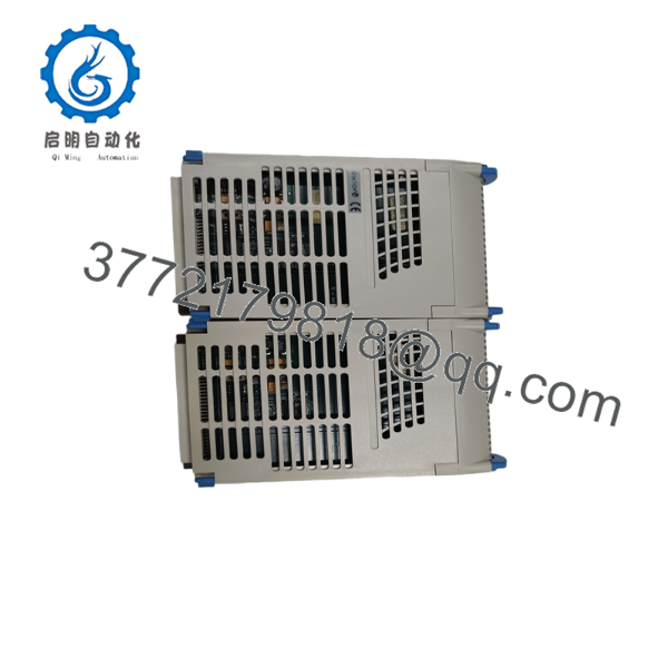
1C31179G01
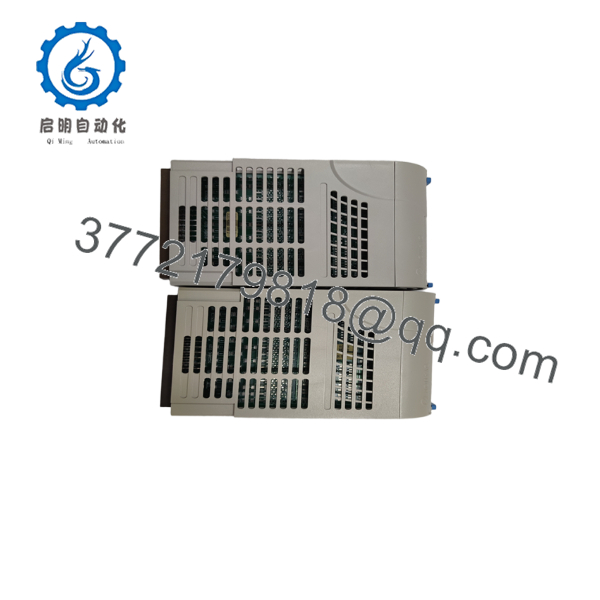
1C31179G01
Stage 4 — Power-On & Testing — 10–15 min
- Before energizing, verify the cabinet power conditions with a multimeter.
- Restore power according to the approved Ovation startup procedure.
- Observe module and MAU status indications.
- Confirm that the Ovation controller recognizes the remote I/O path.
- Verify communication with the applicable remote node.
- Check both channels where the installation uses the two-channel configuration.
- Perform a controlled I/O communication test rather than immediately returning the entire process to automatic operation.
- Verify alarm/status points at the controller level.
- Compare the observed behavior against the pre-replacement baseline.
- Do not increase optical link length or change wavelength simply because the new electronics module powers up normally. The PMOD and optical configuration determine the supported link arrangement.
Supplier Acceptance / QC Checklist
For a shutdown-critical spare, request an acceptance record covering:
- Inbound part-number and serial-number traceability
- Visual inspection of PCB, connectors, housing, and labels
- ESD-controlled handling and packaging
- Power-up verification on an appropriate Ovation test setup
- Communication/MAU functional verification where test facilities are available
- Firmware/configuration identification where applicable
- Electrical safety checks appropriate to the module and test procedure
- Final QC inspection and ESD packaging
For legacy equipment, a test report is more useful than a generic “tested” statement. Ask the supplier what was actually tested and under what system configuration.
Technical Pitfall & Survival Guide
1. G01 vs. G02 confusion
The Ovation documentation distinguishes 1C31179G01 and 1C31179G02 MAU electronics modules. Do not substitute one based only on physical appearance. Match the existing system architecture and module group.
2. PMOD mismatch
The electronics module is only one half of the MAU interface. The 1C31181-series PMOD determines the optical interface configuration. A 1C31179G01 installed with the wrong PMOD can produce a hardware configuration that does not match the installed fiber network.
3. Optical wavelength mismatch
850 nm and 1300 nm configurations are not interchangeable by assumption. Emerson’s documentation specifically states that an Ovation Controller cabinet MAU must use the same optical type for the remote nodes it interfaces with.
4. Link-distance assumptions
The documented 1C31179G01 + 1C31181G01 configuration supports up to 2 km / 6,560 ft. The documentation also recommends not exceeding 3.7 km in MAU applications to avoid requiring extended PCRR timeout periods.
5. Legacy procurement risk
The 1C31179G01 is identified by aftermarket sources as discontinued, while surplus and unused-original listings remain available. That makes nameplate verification, condition verification, and functional testing important procurement controls.
Frequently Asked Questions (FAQ)
1. What is Emerson 1C31179G01?
1C31179G01 is the Electronics Module for the Ovation Remote I/O Media Attachment Unit (MAU). It houses the Attachment Unit Logic Board and works with a compatible 1C31181-series Personality Module.
2. Which PMOD is normally paired with 1C31179G01?
For the documented 850 nm, two-channel, up-to-2 km configuration, the corresponding PMOD is 1C31181G01. Other 1C31181 variants provide different channel, wavelength, and link-length configurations.
3. Is 1C31179G01 obsolete?
It is a legacy Ovation component, and aftermarket documentation identifies it as discontinued by the manufacturer. Existing Ovation installations can still require this module as a maintenance spare.
4. Can I replace 1C31179G01 with 1C31179G02?
Do not make that substitution without checking the installed MAU configuration. The Ovation reference table assigns G01 and G02 to different channel configurations and associated PMODs.
5. What should I verify before purchasing a replacement?
At minimum, verify the complete part number, G-code revision, existing PMOD, optical wavelength, channel count, remote-node configuration, and physical condition. For a critical shutdown spare, request photographs of the actual nameplate and a functional-test record.
6. Does buying a surplus 1C31179G01 guarantee an OEM warranty?
No. Warranty depends on the seller and product condition. Current aftermarket listings may provide their own warranty, which is different from an Emerson factory warranty.
7. What is the biggest installation risk?
The most common serious mistake is treating the electronics module as an isolated replacement and ignoring the PMOD/optical configuration. Verify the complete MAU chain before returning the remote I/O system to service.



