WhatsApp: +86 16626708626
 Email:
 Phone: +86 16626708626
Description
Core Product Summary
The Emerson VE4002S1T2B1 is a DeltaV discrete output card belonging to the M-Series Traditional I/O family for the Emerson DeltaV distributed control system. It provides eight output channels for switching 24 VDC field loads, with each channel switching on the high side — the positive leg of the field circuit — which avoids carrying current in the field wiring when no output signal is present. The complete I/O interface consists of this card together with the standard 8-channel I/O terminal block, mounted on a DIN-rail I/O interface carrier.
Each channel is rated 1.0 A continuous, with a maximum of 3.0 A per I/O interface, and the card accepts an output range of 2 to 60 VDC. Channels can be configured as discrete, momentary (100 ms to 100 s), or continuous pulse outputs. Every channel is optically isolated from the system and factory tested to 1500 VDC, and the card supports simplex or redundant installation on a redundant terminal block.
Key Technical Specifications
| Parameter | Value |
|---|---|
| Product type | Discrete output card, DeltaV M-Series Traditional I/O |
| System family | Emerson DeltaV |
| Number of channels | 8 |
| Output type | High side (switching on the positive leg of the field circuit) |
| Output range | 2 VDC to 60 VDC |
| Output rating | 1.0 A continuous per channel; 3.0 A maximum per I/O interface |
| Off-state leakage | 1.2 mA maximum |
| Isolation | Each channel optically isolated from the system, factory tested to 1500 VDC |
| LocalBus current (12 VDC nominal) | 100 mA typical, 150 mA maximum per card |
| Field circuit power | 3.0 A at 24 VDC per I/O interface |
| Optional fuse | 2.0 A |
| Configurable channel types | Discrete output; momentary output (100 ms to 100 s); continuous pulse output (100 ms to 100 s base period, 5 ms resolution) |
| Operating temperature | ‘-40 to 70 °C (-40 to 158 °F) |
| Storage temperature | ‘-40 to 85 °C (-40 to 185 °F) |
| Relative humidity | 5 to 95%, non-condensing |
| Protection rating | IP20, NEMA 12 enclosure |
| Airborne contaminants | ISA-S71.04-1985 Class G3 (conformal coated) |
| Card dimensions (common I/O interface form factor) | H 10.7 cm × W 4.1 cm × D 10.5 cm (4.2 × 1.6 × 4.1 in.) |
Engineering Selection Highlights
- 8 high-side channels at 24 VDC — sized for solenoid valves, relays, and other DC field loads where switching on the positive leg is required by the grounding or wiring scheme.
- 1.0 A continuous per channel, 3.0 A per I/O interface — the interface-level budget, not just the per-channel rating, governs total load on one card; verify aggregate current before populating all eight channels at full load.
- Output range 2 to 60 VDC — the card is not limited to a nominal 24 VDC supply; it can switch loads anywhere within this range, which matters when the card is supplied through a different field power leg.
- Standard 8-channel I/O terminal block — this orderable configuration uses the standard terminal block; fused, mass-termination, and redundant 8-channel blocks exist within the family, so confirm the terminal block variant matches the existing carrier wiring.
- Optical isolation, 1500 VDC factory test per channel — separates field circuits from the system side without channel-to-channel isolation claims; channels share a common return arrangement on the high-side design.
- Simplex or redundant installation — the same card can serve as a redundant pair on a two-wide redundant terminal block, with autosensing by the controller and automatic switchover on fault.
- 1.2 mA maximum off-state leakage — relevant when driving low-current or sensitive loads that may partially energize from leakage current.
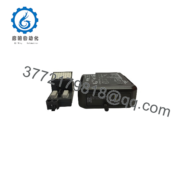
VE4002S1T2B1
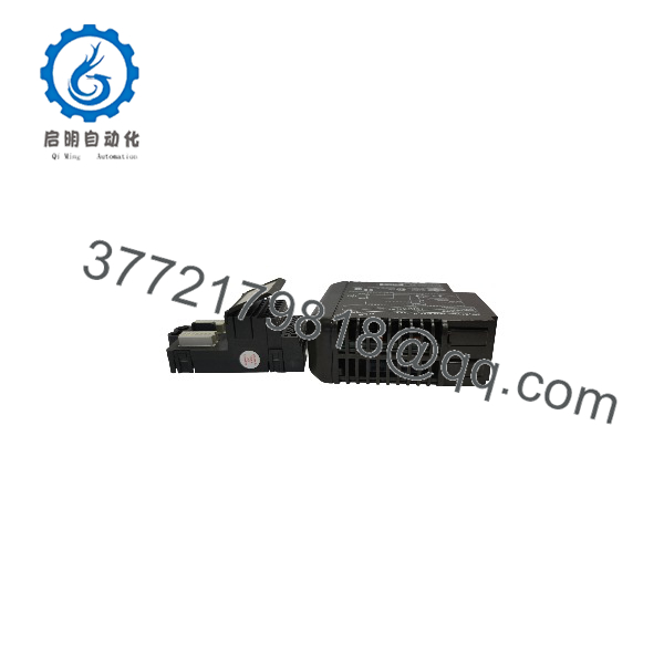
VE4002S1T2B1
System Compatibility & Integration Requirements
| Item / Dependency | Verified Compatibility or Requirement | Practical Note |
|---|---|---|
| Control system | DeltaV DCS, M-Series Traditional I/O subsystem | Card is recognized and configured through DeltaV system tools; new I/O is acknowledged with basic configuration assigned automatically. |
| Mounting | I/O interface carrier (DIN-rail mounted) | All I/O components plug onto the carrier; the carrier can be installed before cards and terminal blocks are added. |
| Terminal block | Standard 8-channel I/O terminal block | Terminal blocks can be pre-wired before card installation; each I/O interface is uniquely keyed so a keyed slot accepts only the correct card type. |
| Keying | Function/field wiring protection keys | Prevents installation of an incorrect card into a keyed terminal block position. |
| Field power | 24 VDC bulk power for field devices, 3.0 A per I/O interface | Field circuit power is supplied per I/O interface, not per channel. |
| Redundancy | Two-wide redundant terminal block required for redundant pair | The controller autosenses a redundant pair; switchover completes within two scans of the I/O bus, with make-before-break contacts keeping digital loads powered. |
| Under-power replacement | Cards may be replaced under power in safe areas | In hazardous areas, applicable installation procedures must be followed. |
| Optional fuse | 2.0 A | In-line fusing supports field wiring protection on the terminal block. |
Dimensions, Mounting & Connection Notes
- Common I/O interface form factor: 10.7 cm high × 4.1 cm wide × 10.5 cm deep (4.2 × 1.6 × 4.1 in.).
- The card plugs directly into a slot on the I/O interface carrier; no separate mounting hardware is used for the card itself.
- Field wiring is 2-wire, non-arcing (or non-sparking, -nA) per the manufacturer’s field wiring classification for this card type.
- An optional 2.0 A fuse supports the output circuits.
- Housing is labeled with the card type; cards carry power and internal error indicators, and 8-channel cards provide visible channel status LEDs.
- Environmental installation limits: -40 to 70 °C operating, 5–95% relative humidity non-condensing, IP20 requiring a NEMA 12 enclosure, ISA G3 corrosion resistance via conformal coating.
Detailed Product Overview
The VE4002S1T2B1 is one variant within Emerson’s DeltaV M-Series Traditional I/O discrete output range. Its position in the order code family is defined by two attributes: it is the 8-channel, 24 VDC high-side output card, delivered as an I/O interface with the standard 8-channel terminal block. Understanding those two attributes covers most selection decisions an engineer will make.
The high-side topology is the first distinguishing attribute. The card switches the positive leg of each output circuit, which means the load is connected between the output terminal and the common return. In practical wiring terms, this avoids current flowing in the field wiring when the output is off, simplifying grounding schemes where the negative leg is common. It contrasts with the isolated variant in the same family, which provides channel-to-channel isolation and a different terminal block; the two should not be treated as interchangeable despite similar channel counts and voltage ratings.
The second attribute is load capacity. Each channel sustains 1.0 A continuous, but the I/O interface as a whole is limited to 3.0 A of field circuit power at 24 VDC. A design that loads several channels near their individual ratings will hit the interface budget before the per-channel limit, so aggregate loading must be checked during cabinet design, not just per-point sizing. The off-state leakage of 1.2 mA maximum is another value worth attention: sensitive loads with low holding currents can appear partially energized when driven by solid-state outputs with this leakage level.
Integration into the DeltaV system follows the Traditional I/O model. The card plugs into a DIN-rail-mounted I/O interface carrier, and the terminal block plugs onto the carrier independently — which allows field wiring to be completed and terminated before the card is inserted. Function keys on the card and terminal block mechanically prevent the wrong card type from being installed in a keyed slot, so a replacement during maintenance can only land in a correct configuration. The card requires no calibration and reports hardware integrity through system alerts; when a redundant pair is installed on a two-wide redundant terminal block, the controller treats the pair as one card, scans both, and switches over automatically on a detected fault, completing the switchover within two I/O bus scans.
Channel-level configuration is handled in the DeltaV engineering environment. Discrete channels hold the last state submitted by the controller; momentary channels remain active for a configured time between 100 ms and 100 s; continuous pulse channels modulate output activity as a percentage of a configured base period with 5 ms resolution. This makes one hardware type usable for straightforward interlock outputs as well as timed-pulse duties without additional components.
Applications & System Role
Within a DeltaV control architecture, the VE4002S1T2B1 sits in the I/O layer between the controller and discrete field devices. The controller writes output states over the I/O bus, and the card switches the positive leg of each 24 VDC field circuit to drive loads such as solenoid valves, relay coils, indicator lamps, and starter interposing relays. Because Traditional I/O is designed for field-mounted installation near the devices, this card typically serves cabinet- or junction-box-level I/O aggregation close to the process rather than in a centralized marshaling rack.
The configurable channel types extend its role beyond simple on/off control: momentary outputs support timed pulse applications such as valve pulsing or alarm acknowledgment, and continuous pulse outputs support duty-cycle-controlled applications within the 5 ms resolution limit. On a redundant terminal block, a pair of these cards provides automatic switchover for output channels serving critical loads.
FAQ
What is the Emerson VE4002S1T2B1?
It is a DeltaV M-Series Traditional I/O discrete output card providing 8 high-side output channels for 24 VDC field loads, used with the standard 8-channel I/O terminal block.
Which system does it belong to?
It belongs to the Emerson DeltaV distributed control system, specifically the M-Series Traditional I/O subsystem that mounts on DIN-rail I/O interface carriers.
What are its key specifications?
8 channels, high-side switching, 2–60 VDC output range, 1.0 A continuous per channel, 3.0 A maximum per I/O interface, 1.2 mA maximum off-state leakage, and per-channel optical isolation factory tested to 1500 VDC.
Which terminal block does it require?
This configuration uses the standard 8-channel I/O terminal block; the card-terminal block pair is mechanically keyed so only the correct card type fits a keyed slot.
Can this card be used redundantly?
Yes. The same card supports simplex or redundant installation; a redundant pair is created by installing two cards on a two-wide redundant terminal block, which the controller autosenses and manages with automatic switchover on fault.
What load types can each channel drive?
Channels can be configured as a discrete output, a momentary output active for 100 ms to 100 s, or a continuous pulse output with a 100 ms to 100 s base period and 5 ms resolution.
What installation environment does it support?
Operating range is -40 to 70 °C, 5–95% relative humidity non-condensing, IP20 protection requiring a NEMA 12 enclosure, with conformal coating meeting ISA G3 corrosion specifications.
Can the card be replaced while powered?
In safe areas, failed cards can be replaced under power; in hazardous areas, the applicable installation procedures must be followed.