
 WhatsApp: +86 16626708626
 Email:
  Phone: +86 16626708626
Description
3. Key Technical Specifications
| Parameter | Value |
|---|---|
| Model | 7G4202-60 |
| Product Type | Distributed Forwarding Engine (DFE) |
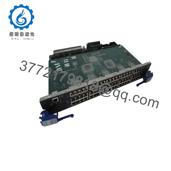
| Ethernet Ports | 60 × 10/100/1000Base-TX RJ45 |
| Switching Capacity | 18 Gbps |
| Maximum Port Speed | 1 Gbps |
| Management | CLI, SNMP v1/v2c/v3, Telnet, RMON |
| Layer Support | Layer 2/Layer 3 (platform dependent) |
| Compatible Platform | Enterasys Matrix N-Series chassis |
| Dimensions | 60.5 × 295.1 × 464.3 mm |
| Weight | Approximately 4.1 kg |
| Compliance | UL 60950, CSA 60950, IEC 60950, EN 60950 |
| Operating Firmware | Verify compatibility before installation |
Compatibility and hardware specifications should always be verified against the installed chassis firmware and OEM documentation before deployment.
4. Product Introduction
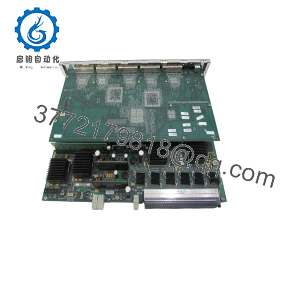
The Enterasys 7G4202-60 is a Distributed Forwarding Engine (DFE) switch module designed for Enterasys Matrix N-Series switching platforms. It provides sixty 10/100/1000Base-T Ethernet interfaces for enterprise campus networks, industrial control environments, and large Layer 2 aggregation deployments.
In field deployments, these modules have proven reliable when installed with firmware matched to the existing chassis. The primary advantage is high port density without requiring a complete chassis replacement, making it a practical option for maintaining legacy Enterasys infrastructures.

- 7G4202-60
5. Installation & Configuration Guide
Stage 1 – Pre-Installation Preparation (10 minutes)
⚠️ Safety First
- Notify operations personnel of scheduled downtime.
- Place the network into a safe maintenance state.
- Lock out and tag out power.
- Wait at least 5 minutes for internal capacitors to discharge.
Tools Required
- Grounded ESD wrist strap
- PH1 screwdriver
- Digital multimeter (Fluke 115 or equivalent)
- Cable labels
- Smartphone for documentation
Data Backup
- Export running configuration.
- Save startup configuration.
- Record management IP addresses.
- Photograph all module positions.
- Photograph DIP switches or jumper settings if applicable.
Stage 2 – Removing the Old Module (5 minutes)
- Remove the front panel if installed.
- Label every connected cable.
- Disconnect cables without pulling on the conductors.
- Release the retaining mechanism.
- Pull the module straight out to avoid damaging the backplane connector.
- Inspect the chassis connector for bent pins, dust, or oxidation.
⚠️ Do not discard the original module until the replacement has completed production testing.
Stage 3 – Installing the New Module (10 minutes)
- Wear an ESD strap before handling the module.
- Verify the model number is exactly 7G4202-60.
- Replicate every hardware configuration from the original module.
- Carefully insert the module until fully seated.
- Tighten retaining screws evenly.
- Reconnect all Ethernet cables.
Self-Checklist
- ☑ Model verified
- ☑ Wiring restored
- ☑ Module fully seated
- ☑ Locking tabs secured
Stage 4 – Power-On & Testing (10 minutes)
Pre-Power Check
- Measure the power rails for shorts.
- Verify chassis power supply status.
Startup Procedure
- Apply power to the chassis.
- Verify LED boot sequence.
- Confirm RUN indicators become normal.
- Connect through the management interface.
- Verify firmware version.
- Restore configuration if required.
- Test VLAN connectivity.
- Verify uplinks and spanning tree operation.
⚠️ Troubleshooting
- Solid ERR LED: Firmware incompatibility is one of the first items to investigate.
- No network communication: Verify management configuration, VLAN assignments, and module seating.
- Intermittent ports: Inspect the chassis backplane connector before replacing the module.
Common Replacement Pitfalls
❗ Firmware Revision Mismatch
This has caused more downtime than defective hardware in many legacy installations. Record the firmware version before removing the original module and request matching firmware whenever possible. I’ve seen maintenance windows extend for hours because a newer firmware revision behaved differently inside an older chassis.
❗ DIP Switch or Configuration Differences
Always photograph every configuration before removal. This simple step prevents the most common field installation mistake.
❗ Backplane Compatibility
Although modules may appear physically identical, firmware qualification varies between hardware revisions. Verify compatibility before installation.
❗ Power Budget
Large chassis with multiple forwarding engines consume considerably more power than lightly populated systems. Leave approximately a 20% power margin when calculating supply capacity.
❗ Electrostatic Discharge
Always use a grounded wrist strap and ESD mat. Static damage often leaves no visible evidence until the module fails during commissioning.
Keep these checks in mind and you’ll avoid most of the rework encountered during legacy Enterasys maintenance.
6. Frequently Asked Questions (FAQ)
Q1. Can I hot-swap the 7G4202-60?
Generally, no. Unless your specific chassis documentation explicitly supports online replacement for this module, power down the chassis first. Hot-swapping unsupported hardware can damage the backplane.
Q2. Is the 7G4202-60 obsolete?
Yes. This is a legacy Enterasys module that is no longer in current production. Most available inventory consists of tested surplus equipment or unused surplus stock.
Q3. Is New Surplus different from refurbished?
Yes.
- New Original (New Surplus): Unused OEM hardware stored after original production.
- Refurbished: Previously deployed hardware that has been cleaned, tested, and verified functional.
Always confirm the condition before ordering.
Q4. Will replacing the module erase my network configuration?
No. Configuration is normally stored by the chassis supervisor or management engine rather than the forwarding module. Even so, always back up the running configuration before maintenance.
Q5. Why is surplus pricing lower than the original OEM list price?
These products are discontinued. Pricing reflects secondary-market availability rather than the original manufacturer price. Supply varies with remaining inventory.
Q6. How do you verify quality before shipment?
Our inspection process includes:
- Serial number verification where available
- Visual inspection for corrosion, repair marks, and connector damage
- Power-on testing in a compatible Enterasys chassis
- Communication verification
- Port functionality testing
- Insulation and continuity checks
- Firmware version documentation
- ESD-safe packaging with final QC inspection
Test photos and operational videos can be provided upon request.



