
 WhatsApp: +86 16626708626
 Email:
  Phone: +86 16626708626
Description
Key Technical Specifications
| Parameter | Specification |
|---|---|
| Manufacturer / Platform | Enterasys / Foxboro-qualified control network equipment |
| Model | A4H124-24FX |
| Foxboro Part Number | P0973JN |
| Product Type | 24-port fiber managed Ethernet switch |
| Main Fiber Ports | 24 × 100Base-FX |
| Fiber Connector | MT-RJ |
| Fixed Copper Ports | 2 × 10/100/1000Base-T, RJ-45 |
| Gigabit Uplink Ports | 2 × 1000Base-X SFP / Mini-GBIC |
| Switching Layer | Layer 2 |
| Supported Functions | VLAN, STP, RSTP, QoS, port mirroring |
| Management | Local console, SNMP/RMON |
| AC Input | 100–240 V AC, 50–60 Hz |
| Maximum Power | 66 W |
| Maximum Current | 0.5 A at 110 V AC; 0.47 A at 220 V AC |
| Operating Temperature | 0 to +50°C |
| Operating Humidity | 5–95% RH, noncondensing |
| Storage Temperature | -40 to +70°C |
| Mounting | Desktop or 19-inch rack, 1U |
| Dimensions | 44.1 × 36.85 × 4.4 cm |
| Approx. Weight | 2.7 kg |
| Contamination Rating | ISA S71.04 Class G1 |
Schneider Electric’s Foxboro documentation identifies P0973JN specifically as the A-Series 24-port fiber managed switch qualified for Foxboro DCS control-network applications. The document specifies 24 × 100Base-FX MT-RJ ports, two fixed 10/100/1000 RJ-45 ports, and two 1000Base-X SFP uplink ports.
The same documentation specifies 100–240 V AC input, 66 W maximum power consumption, 0–50°C operating temperature, 5–95% noncondensing humidity, and 19-inch 1U mounting.
Product Introduction
The Enterasys A4H124-24FX, Foxboro part number P0973JN, is a managed fiber Ethernet switch used as qualified Ethernet equipment within Foxboro process-control networks. Its primary switching interface consists of 24 100Base-FX fiber ports with MT-RJ connectors, supplemented by two fixed tri-speed copper ports and two modular Gigabit uplink ports.
For legacy DCS maintenance, the important distinction is that P0973JN is network infrastructure rather than a Foxboro FBM, controller, or I/O module. Schneider Electric’s Foxboro documentation states that the qualified Ethernet switches are used to interconnect DCS controllers, workstations, and servers. The switch supports VLAN configuration, STP/RSTP, QoS, local console configuration, SNMP/RMON monitoring, and port mirroring.
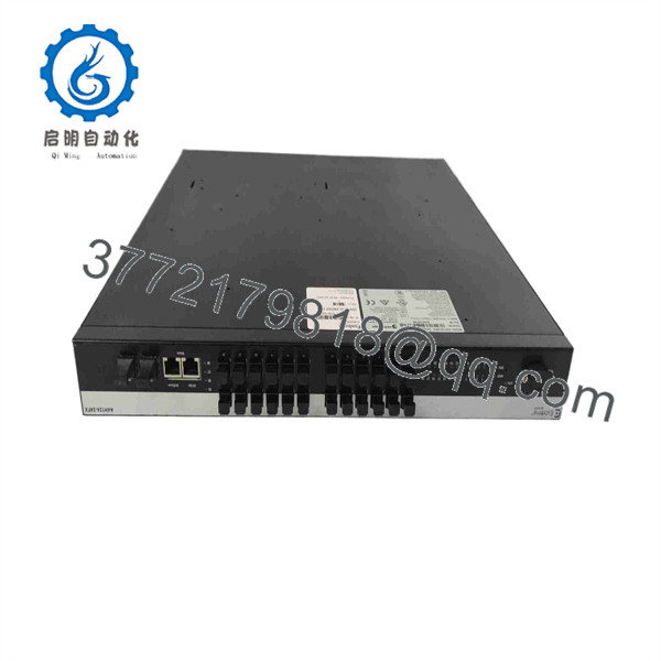
A4H124-24FX P0973JN
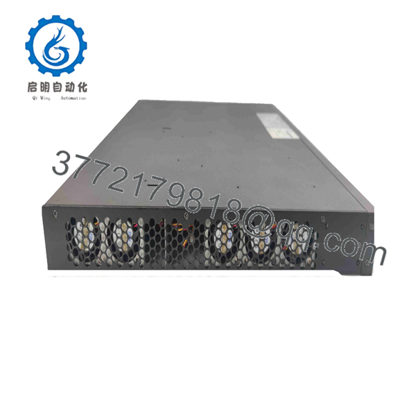
A4H124-24FX P0973JN
Installation & Configuration Guide
Stage 1 — Pre-Installation Preparation
- Confirm the existing equipment label shows A4H124-24FX / P0973JN.
- Verify that the switch is part of the approved Foxboro control-network architecture.
- Record all fiber and copper port assignments.
- Export or document the existing switch configuration before removal.
- Apply the plant’s LOTO procedure before disconnecting power.
- Allow the equipment to discharge for at least 5 minutes after isolation.
- Photograph the front and rear connections before removing the existing unit.
- Confirm that replacement fiber connectors, SFP/Mini-GBIC modules, and cables match the existing installation.
The Foxboro documentation specifies a minimum 5.1 cm (2.0 in) clearance around the switch for ventilation. The installation area should also maintain the specified 0–50°C ambient range.
Stage 2 — Removing the Existing Switch
- Place the control network in the approved maintenance state.
- Identify every active fiber and copper port.
- Record the existing port-to-device mapping.
- Disconnect the AC input after confirming isolation.
- Carefully disconnect the MT-RJ fiber connections without contaminating the fiber endfaces.
- Remove installed SFP/Mini-GBIC modules if they are being transferred.
- Remove the switch from its shelf or 19-inch rack position.
- Inspect the rack hardware, power connection, and fiber connectors for damage.
Do not pull or bend fiber cables sharply during removal. Preserve the original port mapping until network commissioning is complete.
Stage 3 — Installing A4H124-24FX P0973JN
- Verify the replacement part number before mounting.
- Install the switch in the existing shelf or 19-inch rack position.
- Secure the chassis mechanically.
- Install the required 1000Base-X Mini-GBIC modules in the designated SFP ports.
- Reconnect the 24 fiber ports according to the recorded port map.
- Reconnect the two RJ-45 uplink/device ports where applicable.
- Verify the AC supply is within 100–240 V AC, 50–60 Hz.
- Check ventilation clearance before applying power.
The two Gigabit SFP ports are modular uplink interfaces; they are not interchangeable with the 24 fixed 100Base-FX MT-RJ ports.
Stage 4 — Power-On & Testing
After installation:
- Energize the switch and check its status indicators.
- Verify that the expected fiber links establish correctly.
- Confirm copper uplinks negotiate at the expected speed.
- Check VLAN configuration against the approved network design.
- Verify STP/RSTP status where implemented.
- Confirm management access through the approved console or network-management method.
- Check SNMP/RMON monitoring if used by the Foxboro control network.
- Perform point-to-point communication checks with connected controllers, workstations, or servers.
- Verify network redundancy and uplink paths before returning the control network to normal operation.
Critical Compatibility Checks
Do not confuse with P0973JM. P0973JM is the A-Series 24-port copper managed switch, while is the 24-port fiber version. Schneider’s Foxboro documentation explicitly distinguishes the two part numbers.
Check the fiber connector. ‘s 24 main switch ports use MT-RJ connectors. The SFP uplinks use modular Mini-GBIC interfaces.
Check the power arrangement. The switch has internal 100–240 V AC input and supports an optional redundant power supply. If redundancy is installed, the documentation calls for separate branch circuits.
Do not apply modern industrial-switch specifications from unrelated A-Series listings. Some secondary listings incorrectly describe this exact part as a DIN-rail, 24 V DC, IP-rated industrial switch. The Foxboro-qualified documentation specifies a 1U rack/shelf design, 100–240 V AC input, 0–50°C operation, and MT-RJ fiber ports.
Frequently Asked Questions (FAQ)
1. What is Enterasys A4H124-24FX ?
It is a 24-port fiber managed Ethernet switch in the Enterasys A-Series. Foxboro documentation identifies as the Foxboro-qualified part number for this switch in its control-network equipment portfolio.
2. How many fiber ports does have?
The switch provides 24 × 100Base-FX fiber ports, using MT-RJ connectors. It also has two fixed 10/100/1000 RJ-45 ports and two 1000Base-X SFP uplink ports.
3. Is a Foxboro DCS I/O module?
No. It is a control-network Ethernet switch. It provides network connectivity between Foxboro DCS equipment such as controllers, workstations, and servers; it does not function as an FBM or controller.
4. What power supply does A4H124-24FX use?
The published Foxboro specification calls for 100–240 V AC, 50–60 Hz, with maximum power consumption of 66 W. The unit also supports an external redundant power supply option.
5. What is the operating temperature?
The specified operating temperature is 0 to +50°C (32 to +122°F), with operating humidity of 5–95% RH, noncondensing. Storage temperature is specified as -40 to +70°C.
6. Can be replaced by another A4-Series switch?
Not automatically. P0973JM, for example, is a 24-port copper model, while is the fiber model. The replacement must match the installed fiber topology, connector type, uplink configuration, power arrangement, and Foxboro network design.
7. What should be verified before purchasing a replacement?
For a live Foxboro control network, verify:
- 24 × 100Base-FX MT-RJ ports
- Existing Mini-GBIC/SFP modules
- Fiber type and connector arrangement
- Existing VLAN/STP/RSTP configuration
- AC input and redundant-power arrangement
- Hardware condition and revision
- Configuration backup availability
- Exact Foxboro network application
Because this is legacy control-network hardware, a physically similar Ethernet switch should not be treated as a direct replacement unless its network functions and Foxboro qualification have been checked against the installed system.



