
 WhatsApp: +86 16626708626
 Email:
  Phone: +86 16626708626
Description
3. Key Technical Specifications
| Parameter | Value |
|---|---|
| Model | B5G124-48P2 |
| Product Type | Stackable Layer 2/Layer 3 Managed Switch |
| Access Ports | 48 × 10/100/1000Base-T RJ45 with IEEE 802.3af/802.3at PoE+ |
| Fiber Interfaces | 4 × Combo 1000Base-X SFP |
| Stack Ports | 2 × Dedicated High-Speed Stacking Ports |
| PoE Standard | IEEE 802.3af / IEEE 802.3at |
| Maximum PoE Output | Up to 30 W per port |
| Switching Capacity | 96 Gbps (Standalone) |
| Forwarding Rate | 71.4 Mpps (Standalone) |
| MAC Address Table | 32,000 Entries |
| VLAN Capacity | 4,093 VLAN IDs |
| QoS Queues | 8 Hardware Queues per Port |
| Management | CLI, SNMP, Web Management, RMON |
| Stack Size | Up to 8 Switches |
| Power Input | 100–240 VAC, 50/60 Hz |
The B5 Series supports dual-stack IPv4/IPv6 management, Layer 2/3/4 packet classification, policy-based automation, and hardware stacking for up to eight switches.
4. Product Introduction
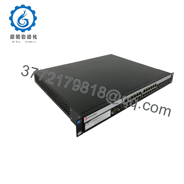
The Enterasys B5G124-48P2 is a high-density Gigabit Ethernet stackable switch designed for enterprise edge, campus access, and industrial network deployments. It provides forty-eight Gigabit PoE+ access ports, four combo SFP interfaces, and dedicated stacking ports to support scalable network expansion without requiring additional aggregation hardware.
From practical deployment experience, the B5 Series remains a dependable choice for organizations maintaining existing Enterasys infrastructures. Its support for IEEE 802.3at PoE+, Layer 3 routing, hardware stacking, and mature management software allows legacy networks to continue operating without major architectural changes.
5. Installation & Configuration Guide
Stage 1 – Pre-Installation Preparation (10 Minutes)
⚠️ Safety First
- Notify operations of the planned maintenance window.
- Save the current switch configuration.
- Disconnect AC power and perform Lock-Out/Tag-Out.
- Wait at least 5 minutes before servicing the hardware.
Tools Required
- Grounded ESD wrist strap
- PH1 screwdriver
- Fluke 115 digital multimeter
- Cable identification labels
- Smartphone for wiring documentation
Data Backup
- Export startup configuration.
- Save running configuration.
- Record management IP address.
- Photograph every RJ45 and SFP connection.
- Document stack member numbers.
- Record the installed firmware version.
Stage 2 – Removing the Existing Switch (10 Minutes)
- Label every copper and fiber connection.
- Remove SFP transceivers carefully.
- Disconnect Ethernet cables.
- Disconnect AC power.
- Remove rack mounting screws.
- Slide the switch out evenly without twisting the chassis.
⚠️ Retain the original switch until the replacement has passed all operational testing.
Stage 3 – Installing the Replacement (10–15 Minutes)
- Wear a grounded ESD wrist strap.
- Verify the replacement model is exactly B5G124-48P2.
- Install the switch in the rack.
- Secure all mounting hardware.
- Reinstall SFP modules in their original locations.
- Restore network cabling.
- Reconnect stack cables before applying power.
Self-Checklist
- ☑ Model number confirmed
- ☑ Stack cables connected
- ☑ Fiber modules installed
- ☑ Ethernet cables secured
- ☑ Ground connection verified
Stage 4 – Power-On & Testing (15 Minutes)
Pre-Power Check
- Measure AC input voltage.
- Verify there are no shorts.
- Confirm stack cables are fully seated.
Startup Procedure
- Apply power.
- Observe POST and LED status.
- Verify the switch boots normally.
- Connect through the console or management interface.
- Confirm firmware revision.
- Restore the saved configuration if required.
- Verify VLAN operation.
- Test PoE delivery.
- Confirm stack membership.
- Verify uplink connectivity.
⚠️ Troubleshooting Notes
- Solid fault LED: Verify firmware compatibility across all stack members.
- Stack does not form: Check stack cable orientation and ensure all switches run compatible firmware.
- PoE devices fail to power: Verify available PoE power budget and port priority configuration.

- B5G124-48P2
- B5G124-48P2
Common Technical Pitfalls
❗ Firmware Revision Mismatch
This is probably the issue I’ve encountered most often on B5 deployments. Replacing a single stack member with a significantly newer firmware revision can prevent the stack from forming correctly. Record the firmware version before removing the original unit and request matching firmware whenever possible.
❗ Stack Cabling Errors
The dedicated stack ports are not ordinary Ethernet uplinks. Verify cable orientation carefully. A crossed or loose stack cable can leave the replacement switch operating as an independent unit instead of joining the stack.
❗ SFP Compatibility
Even if a third-party SFP works electrically, legacy Enterasys platforms may reject unsupported optics. Confirm the transceiver type before commissioning.
❗ PoE Power Planning
A fully populated switch supplying 30 W to every port places a substantial load on the internal power system. Calculate the total PoE demand before connecting wireless access points, IP cameras, and VoIP phones simultaneously.
❗ Electrostatic Discharge (ESD)
Always wear a grounded wrist strap. I’ve seen perfectly functional replacement switches develop intermittent interface faults simply because ESD precautions were ignored during installation.
Keep these checks in mind and you’ll eliminate most of the troubleshooting typically encountered during B5 Series replacements.
6. Frequently Asked Questions (FAQ)
Q1. Can the B5G124-48P2 be hot-swapped?
No. This is a standalone stackable switch rather than a chassis module. Power down the unit before replacement to avoid hardware damage or configuration issues.
Q2. Does this model support IEEE 802.3at PoE+?
Yes. All forty-eight RJ45 access ports support IEEE 802.3af and IEEE 802.3at, delivering up to 30 W per port for devices such as wireless access points, PTZ cameras, and IP phones.
Q3. How many switches can be stacked together?
The B5 Series supports stacking of up to eight switches, allowing centralized management and simplified network expansion while operating as a virtual switch.
Q4. Will replacing the switch erase my network configuration?
Not if you’ve backed it up. Export both the startup and running configurations before maintenance. After installing the replacement, restore the saved configuration and verify stack membership.
Q5. Why is New Surplus equipment less expensive than the original OEM price?
The B5 Series has reached end-of-sale status. Current market pricing reflects surplus inventory availability rather than the original factory list price. New Surplus units are unused OEM inventory, while refurbished units have been previously deployed and fully tested.
Q6. What quality inspections are completed before shipment?
Every B5G124-48P2 undergoes a documented inspection process that includes:
- OEM model and serial number verification
- Visual inspection for corrosion, connector wear, scratches, and repair marks
- Power-on self-test
- RJ45 port verification
- PoE functionality testing
- SFP communication testing
- Stack interface verification
- Firmware version documentation
- Final QC approval
- ESD-safe packaging with anti-static protection and heavy-duty shipping materials
Power-on videos, functional test reports, and inspection photographs are available upon request.



