
 WhatsApp: +86 16626708626
 Email:
  Phone: +86 16626708626
Description
Key Technical Specifications
| Parameter | Value |
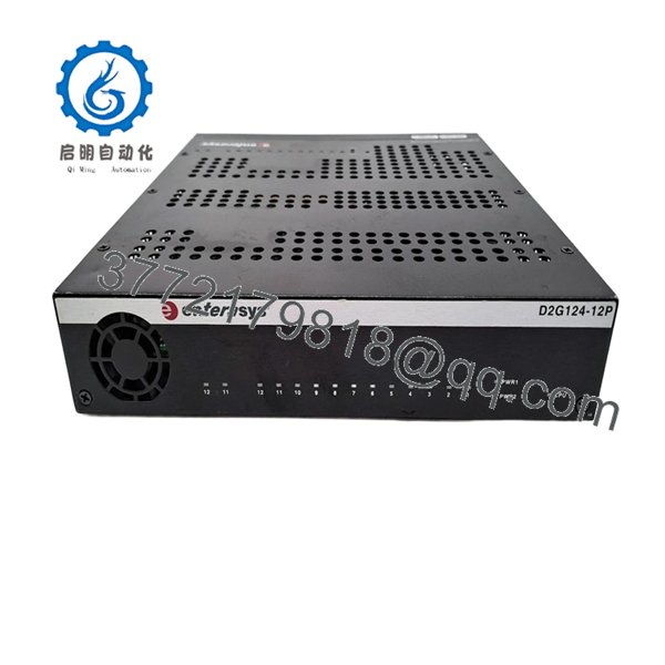
| Port Layout | 24 x 10/100/1000BASE-T RJ-45 total ports (12 ports with PoE, 12 ports standard data-only) |
| Uplink Expansion | 4 x SFP Gigabit Ethernet combo ports (shared with ports 21 through 24) |
| PoE Allocation | 12 ports compliant with IEEE 802.3af Power over Ethernet standard |
| Architecture Base | Wire-speed Layer 2 packet switching and Layer 3 hardware routing engine |
| Policy Engines | Dynamic user-based policy assignment and Layer 2/3/4 multi-field ACL mapping |
| Stacking Capacity | SummitStack-compatible or virtual stacking architecture depending on active firmware flags |
| Enclosure Setup | 1RU rack-mountable industrial-grade metal casing |
| Dimensions | 17.32 x 11.42 x 1.73 inches (44.0 x 29.0 x 4.4 cm) |
| Shipping Weight | Approximately 11.80 lbs (5.35 kg) |
Product Introduction & Supply Chain Strategy
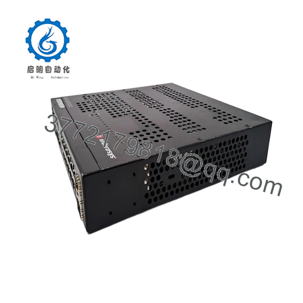
The Enterasys D2G124-12P is a specialized, secure Layer 3 workgroup switch engineered to supply fine-grained network control and localized Power over Ethernet for industrial manufacturing cells, processing lines, and remote site offices. Designed with a hybrid port layout, the switch supplies 12 specialized ports equipped with IEEE 802.3af PoE to energize edge units like terminal controllers, surveillance cameras, and proximity readers, alongside 12 standard non-powered data channels. Driven by Enterasys’ native policy framework, this system provides hardware-enforced security rules and packet sorting profiles directly at the hardware ingestion boundary, insulating critical operational control loops from broader network noise.
As the Matrix D2 family has long passed its official End-of-Life boundaries, securing this switch as a New Surplus asset represents a key supply chain risk-management strategy. Deploying low-tier refurbished or decommissioned hardware into legacy fields presents high failure profiles, including failing internal capacitors and weakened PoE switching paths that introduce erratic port cycling. Purchasing un-deployed, original factory-packaged inventory preserves your facility’s Total Cost of Ownership by securing a pristine 10-to-15 year hardware lifecycle, ensuring uninterrupted packet delivery, and protecting your automation layouts from prolonged, unbuffered downtime.
Installation & Configuration Guide
Stage 1: Pre-Installation (Prep & Safety)
- Completely isolate the input power routing to the dedicated network rack node. Ensure that any machinery tied to down-link switches is safely paused.
- Fasten an ESD anti-static wrist strap to your arm and connect its grounding clip to a bare, unpainted metal quadrant of the equipment enclosure frame.
- Access the existing D2 switch interface via the serial console and execute the
show configandshow systemdiagnostic routines; save this configuration log to a remote engineering directory to map your VLAN parameters and interface settings. - Document the copper connection layouts by taking sharp photographs of the existing port interface wiring matrix to avoid line cross-mapping.
Stage 2: Removal
- Unplug the main AC power cord from the rear socket panel. If an external redundant power rail auxiliary system is integrated, isolate the connector terminal completely.
- Unlatch the retaining clasps on any active fiber optic SFP transceivers, pull them cleanly from the combo ports, and snap protective dust covers over the exposed optical lenses.
- Gently pull out the 24 RJ-45 network patch cables, taking care not to pinch or shear off the integrated locking tabs.
- Support the weight of the module casing, unbolt the four retaining screws from the chassis rack ears, and slide the switch assembly forward out of the rails.
Stage 3: Installation (Clone & Seat)
- Unbox the New Surplus D2G124-12P switch within your static-shielded workstation and check all copper interfaces and chassis edges for physical shipping stress.
- Align the switch housing with the target 1RU space, slide it smoothly into the rack guide slots, and tighten the four front rack ear screws into the vertical rails.
- Re-engage the fiber optic SFP transceivers into their designated combo slots (interfaces 21–24), ensuring they slide home until they latch.
- Plug all 24 copper network patch cables into their original corresponding port destinations based on the records saved in Stage 1.
Stage 4: Power-On & Testing
- Re-seat the primary AC line cord into the rear integrated power supply socket.
- Track the front status lamp array during the boot sequence; verify that the primary power indicators settle into a solid green state, confirming that the initial diagnostic self-test has cleared cleanly.
- Establish a local connection to the RJ-45 serial console interface using an emulation platform set to 9600 baud, 8 data bits, no parity, and 1 stop bit.
- Access the Enterasys prompt, load your backed-up layout parameters via TFTP or manual script input, and execute a configuration write commit to flash storage.

- D2G124-12P
- D2G124-12P
Firmware/Software Versions & Upgrade Notes
The Matrix D2 family functions on explicit firmware binaries developed to preserve role-based policy enforcement across legacy infrastructures. To ensure proper operations, replacement elements must be verified against your system’s standardized baseline images.
⚠️ CRITICAL FIRMWARE INTEGRATION WARNING: Before inserting this New Surplus switch into an active management cluster or stacking matrix, run a standalone boot configuration check to identify its pre-loaded image layer. Attempting to link a switch running an unaligned or older major firmware block (such as an early 5.x build) directly with an active network line using version 6.x code can cause immediate management bus synchronization failures, drop port authentication strings, or drop down-link equipment offline. Always match firmware images via a serial console connection prior to final deployment.
Frequently Asked Questions (FAQ)
What makes this New Surplus D2 switch a better investment than a cheap refurbished alternative?
A New Surplus D2G124-12P switch ensures that all 12 specialized PoE channels, internal power rails, and physical port contact pins are in pristine, un-degraded condition. Refurbished alternatives found on secondary broker channels are typically pulled from long-running server environments where they have endured extensive thermal fatigue under continuous load. This exposure degrades internal capacitors, increasing the risk of intermittent frame drops and unexpected control link failures.
Can I run PoE devices on all 24 ports of this switch?
No. The D2G124-12P features a hybrid architecture. Only the first 12 ports (ports 1 through 12) are wired internally to supply IEEE 802.3af PoE power. Ports 13 through 24 are standard non-powered data channels engineered strictly for connecting line-powered workstations, computers, and standard automation controllers that possess independent power feeds.
How do the 4 SFP combo slots interact with the standard copper ports?
The 4 SFP slots are shared combo interfaces paired mechanically with the last four copper Gigabit ports (ports 21 through 24). If you mount an optical SFP transceiver into one of these expansion bays to handle a long-distance fiber backbone link, the internal switching logic automatically breaks the connection to the corresponding copper RJ-45 port directly adjacent to it. You cannot utilize the copper port and its paired SFP slot simultaneously.
What should I do if the switch prompt demands an administrative login password during configuration?
Every New Surplus unit undergoes final factory quality checks and is cleared back to original factory defaults prior to shipping. In the rare event that you encounter a localized authentication block during your terminal setup, connect a console cable, cycle the main power feed, interrupt the boot routine using the escape key during the BootROM countdown phase, and execute the standard factory password wipe command string.
Will this switch continue to retain my custom policy configurations if input power is cut?
Yes. The switch commits your operating configuration parameters, security access control lists, and VLAN routing frameworks directly to its internal, non-volatile flash file system. Because this architecture is independent of a volatile internal backup battery, a sudden facility power outage will not wipe your active parameters. The system will cleanly re-initialize your parameters once input power stabilizes.
What exact warranty coverage accompanies this legacy Enterasys switch?
We provide a comprehensive 1 year operational warranty covering all integrated component paths, the hybrid port matrix, and the internal power transformation components. If any hardware elements display an electrical fault or run into component degradation while working under nominal operating limits within this protection frame, our team will source a replacement switch to preserve your system runtime.



