
 WhatsApp: +86 16626708626
 Email:
  Phone: +86 16626708626
Description
3. Key Technical Specifications
| Parameter | Value |
|---|---|
| Ethernet Ports | 12 × 10/100BASE-TX RJ45 |
| Switching Type | Managed Layer 2 Industrial Switch |
| Power Input | Dual redundant 24 VDC inputs |
| Mounting | DIN rail (optional rack-mount kit available) |
| Management | CLI, SNMP v1/v2/v3, Telnet, TFTP |
| MAC Address Table | 8,000 entries |
| VLAN Support | Up to 1,024 VLANs |
| Link Aggregation | IEEE 802.3ad |
| Memory | 256 MB SDRAM |
| Flash Memory | 32 MB |
| Dimensions | 8.89 × 33.86 × 18.41 cm |
| Weight | Approximately 4.35 kg |
| MTBF | Approximately 182,146 hours |
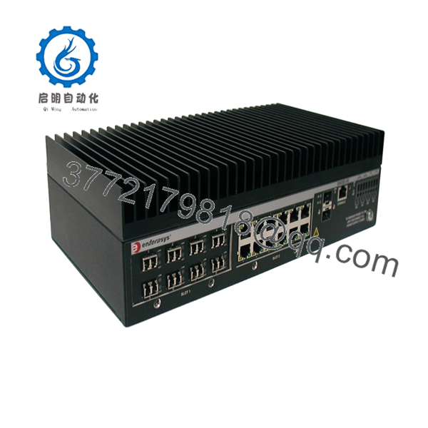
The I3H252-12TX is a factory-configured I-Series switch equipped with one I3H-12TX 12-port 10/100BASE-TX I/O module. It supports redundant industrial power inputs, alarm relays, and industrial Mini-GBIC uplink options depending on the installed configuration.
4. Product Introduction
The Enterasys I3H252-12TX is a hardened industrial Ethernet switch designed for factory automation, transportation systems, power substations, water treatment facilities, and other harsh industrial environments. Unlike traditional office switches, the I-Series platform emphasizes redundant power, alarm monitoring, and high reliability for continuous operation.
Engineers commonly deploy this model inside industrial control cabinets where dependable Fast Ethernet connectivity is required for PLCs, HMIs, RTUs, industrial computers, and remote I/O devices. Although it is now a legacy platform, it remains a practical replacement where existing I-Series infrastructure is still in service.
5. Installation & Configuration Guide
Stage 1 – Pre-Installation Preparation (10 minutes)
⚠️ Safety First
- Notify plant operations of scheduled downtime.
- Follow Lockout/Tagout procedures.
- Remove the 24 VDC supply.
- Wait at least five minutes before servicing.
Tools Required
- Grounded ESD wrist strap
- Phillips screwdriver
- Digital multimeter
- Wire labels
- Smartphone for cable documentation
Data Backup
- Export the running configuration.
- Record IP address and subnet settings.
- Photograph all wiring and terminal connections.
- Document any alarm relay wiring.
- Record the installed firmware version.
Stage 2 – Removing the Existing Switch (5–10 minutes)
- Label every Ethernet cable.
- Disconnect the redundant DC power wiring.
- Remove alarm relay connections.
- Release the DIN-rail latch or rack brackets.
- Remove the switch carefully.
⚠️ Keep the original switch until the replacement has completed functional testing.
Stage 3 – Installing the New Switch (10–15 minutes)
- Verify the replacement model is I3H252-12TX.
- Wear an ESD wrist strap.
- Mount the switch on the DIN rail.
- Connect both redundant power inputs.
- Reconnect Ethernet cables according to the documented layout.
- Restore alarm relay wiring if used.
Self-Checklist
- Model verified
- Dual power connected
- Ground connection secure
- Alarm relay wired correctly
- Ethernet ports restored
Stage 4 – Power-On & Testing (15 minutes)
- Verify the 24 VDC supply voltage.
- Apply primary and secondary power.
- Confirm the Power LEDs illuminate correctly.
- Verify the management interface is accessible.
- Confirm firmware version.
- Restore the saved configuration if required.
- Test Ethernet communications with connected PLCs and controllers.
- Verify alarm relay operation.
⚠️ Troubleshooting Note
If the switch fails to boot correctly, check both DC power inputs before replacing hardware. In industrial installations, wiring errors and incorrect power polarity are encountered more frequently than hardware failures. Firmware mismatches should also be ruled out if configuration restoration fails.

- I3H252-12TX
6. Frequently Asked Questions (FAQ)
Q1. Is the I3H252-12TX designed for industrial environments?
Yes. The I-Series was developed specifically for industrial automation, transportation, utility, and process-control applications. Features such as redundant DC power inputs, alarm relays, and DIN-rail mounting distinguish it from standard enterprise Ethernet switches.
Q2. Does this model support Gigabit Ethernet?
No. The factory-installed I3H-12TX module provides 12 Fast Ethernet (10/100BASE-TX) interfaces. Gigabit connectivity is available only through supported Mini-GBIC uplink configurations on compatible I-Series hardware.
Q3. Is the I3H252-12TX still manufactured?
No. The I-Series is considered a legacy product. Most available units today come from surplus inventories or professionally tested refurbished stock. Organizations typically purchase this model to maintain compatibility with existing industrial control systems.
Q4. Can I hot-swap the switch?
No. The chassis should always be powered down before replacement. Disconnect the 24 VDC supply and verify the control system is in a safe state before removing the unit.
Q5. What is the most common installation mistake?
The most frequent issue is reconnecting the redundant DC power wiring incorrectly or overlooking the alarm relay connections. I’ve seen technicians spend hours troubleshooting network communication when the backup power input had simply been wired with reversed polarity. Taking clear photos before removal prevents most of these mistakes.
Q6. Does the switch support industrial network management?
Yes. The switch supports CLI management, SNMP, VLANs, link aggregation, configuration upload/download, and standard industrial network management functions suitable for managed automation networks.
Q7. What should I verify before ordering a replacement?
Confirm the complete model number, hardware revision, installed I/O module, firmware version, and mounting method. The I-Series platform supports multiple interchangeable I/O modules, so verifying the exact configuration before ordering avoids compatibility problems during installation.



