
 WhatsApp: +86 16626708626
 Email:
  Phone: +86 16626708626
Description
Key Technical Specifications
| Parameter | Value |
| Port Density | 2 x 1000BASE-LX Gigabit Ethernet optical ports |
| Connector Interface | Dual Duplex SC (Subscriber Connector) receptacles |
| Wavelength Profile | 1,310 nm long-wavelength optical transmission |
| Media Support | Single-mode fiber (SMF) and multi-mode fiber (MMF) |
| Max Reach Capacity | Up to 10 km (6.2 miles) on 9/125 µm single-mode fiber core |
| Architecture Base | Wire-speed Layer 3/4 switching and hardware routing engine |
| Chassis Compatibility | Enterasys / Cabletron SmartSwitch Router 8000 (SSR 8000) and SSR 8600 systems |
| Hot-Swap Support | Mechanically designed for live insertion and removal within powered chassis environments |
| Form Factor | Proprietary SSR line card expansion module |
| Shipping Weight | Approximately 4.50 lbs (2.04 kg) |
Product Introduction & Supply Chain Strategy
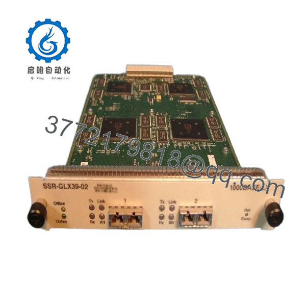
The Enterasys LXSSR-GLX39-02 (also cataloged as the SSR-GLX39-02) is a specialized 2-port 1000BASE-LX Gigabit Ethernet fiber expansion card engineered for the legacy Cabletron / Enterasys SmartSwitch Router (SSR) chassis family. Operating at a 1,310 nm long-wavelength profile over duplex SC connections, this module supplies deterministic wire-speed trunk links extending up to 10 km over single-mode fiber. It serves as a vital uplink vehicle for connecting disparate industrial production clusters, maritime terminal backbones, or localized substation controls to a centralized high-capacity core matrix, effortlessly carrying massive traffic loads without localized jitter or signal dissipation.
As the underlying SSR platform is deeply legacy and completely out of production, deploying this interface module as a New Surplus asset represents a key protective procurement strategy. Secondary-market refurbished components are highly susceptible to silent transmitter diode dimming, unmapped optical path attenuation, and microscopic alignment fractures along the SC barrels that easily pass standard loopback diagnostics but drop packages in erratic intervals under thermal load. Securing original, un-deployed inventory protects your facility’s Total Cost of Ownership by providing pristine optical transceivers, eliminating unexpected packet-loss loops, and mitigating massive emergency replacement delays across your legacy data rings.

- LXSSR-GLX39-02 SSR
Installation & Configuration Guide
Stage 1: Pre-Installation (Prep & Safety)
- Verify the operational budget status of the active SSR-8000 or SSR-8600 chassis. Confirm the specific target slot allocation on your engineering layout map.
- Put on a standard grounded anti-static wrist strap, connecting the alligator lead terminal firmly to the chassis ground plug receiver.
- Access the SSR command-line console interface and run
show systemandshow slotto capture a baseline snapshot of active firmware tags, interface mapping, and routing tables. - Keep the protective plastic dust boots seated inside the dual SC optical ports on the new card until the fiber patch lines are ready for final routing.
Stage 2: Removal
- Unlatch the fiber optic duplex SC patch lines from the ports of the module slated for replacement.
- Immediately snap clean dust caps over the exposed fiber ferrules to protect the glass paths from airborne particulates.
- Completely back out the captive retaining fasteners situated at the left and right borders of the expansion module faceplate.
- Pull the physical ejector tabs outward in a unified motion to unseat the high-density interface connectors from the chassis midplane bus, then slide the card smoothly out along the slot tracks.
Stage 3: Installation (Clone & Seat)
- Extract the New Surplus LXSSR-GLX39-02 module from its anti-static shielding film inside your ESD-controlled work segment. Avoid direct contact with the card traces or optical transmitter blocks.
- Align the outer structural borders of the module logic board with the interior slot guides of the chassis frame.
- Slide the card assembly firmly into the enclosure until the faceplate handles begin to make contact with the outer chassis lip.
- Compress both ejector tabs inward to lock the module pins into the active backplane socket, then torque down the captive retention fasteners to ensure continuous structural seating.
Stage 4: Power-On & Testing
- Remove the protective factory dust caps from the SC barrels and clean the fiber patch connectors using an approved optical lens swipe. Connect the duplex SC fibers to ports 1 and 2.
- Monitor the diagnostic LED indicators on the faceplate; the localized system status light must cycle past initialization and display a steady green state, verifying that internal logic loops have passed check boundaries.
- Access the core administrative console prompt via your engineering terminal and execute the
show slotdiagnostic routine. - Verify that the system registers the replacement module as an active 2-Port 1000BASE-LX interface and confirm that port links show a positive “Up” connection status.
Firmware/Software Versions & Upgrade Notes
The SSR-GLX39-02 expansion engine operates using microcode instructions directly coordinated by the master SmartSwitch Router Operating System (SSR-OS) installed on the control engine processor.
⚠️ CRITICAL FIRMWARE INTEGRATION WARNING: Before initializing this New Surplus optical card within a running, high-availability SSR cluster, ensure that your core chassis SSR-OS version matches the underlying hardware revision state of the new module. Deploying vintage line card designs into systems running modern, final-tier SSR-OS builds without verified patch files can prompt internal register mapping conflicts, prevent the card from initializing its optical ports, or introduce runtime error traps on adjacent modules. Always verify system release documentation before completing physical hardware integration.
Frequently Asked Questions (FAQ)
What makes this New Surplus optical module a better option than a cheap refurbished alternative?
A New Surplus LXSSR-GLX39-02 module ensures that both integrated 1310 nm laser diodes, the internal power regulation circuits, and the physical backplane alignment pins have zero run-time history or material wear. Refurbished equivalents are often salvaged from old, continuously powered enterprise data environments where the optical transmitters have logged thousands of hours. This long-term exposure causes laser degradation, making the module prone to sudden signal drops and link failures.
Can this 1000BASE-LX card operate over multi-mode fiber, or is it strictly single-mode?
This module is natively designed for 1,310 nm long-wavelength transmission over single-mode fiber (SMF) up to distances of 10 km. However, it can also operate over legacy multi-mode fiber (MMF) lines for shorter runs (typically up to 550 meters). When deploying 1000BASE-LX hardware over multi-mode fiber infrastructure, you must install a specialized mode-conditioning patch cable at both ends to prevent differential mode delay (DMD) from destabilizing your link.
Does this card feature standard modern SFP slots for transceiver flexibility?
No. The legacy LXSSR-GLX39-02 is a fixed-configuration line card built before the widespread adoption of hot-swappable Small Form-factor Pluggable (SFP) transceivers. The optical transceivers and dual duplex SC interfaces are soldered directly onto the circuit board architecture. The entire module operates as a dedicated, standalone 2-port 1000BASE-LX fiber asset.
Can I hot-swap this port module while the rest of the SmartSwitch Router chassis is live?
Yes. The mechanical and electrical bus parameters of the Enterasys SSR-8000 and SSR-8600 chassis platforms support the hot-swapping of peripheral port modules. However, if the fiber lines connected to this specific card carry active, non-redundant uplink paths for your production floor, pulling the card will instantly sever those communication streams. Ensure all traffic is redirected before extraction.
What should I do if the module fails to establish a link light after connecting the fiber lines?
First, verify your fiber optic polarity; try crossing the transmit (TX) and receive (RX) strands on one end of the duplex SC cable. Second, ensure that the optical interfaces on both ends of the run match (both must be 1000BASE-LX 1,310 nm devices). If you attempt to connect a 1310 nm LX port directly to an 850 nm SX short-haul port, the interfaces will fail to achieve an optical handshake.
What precise warranty coverage backs this legacy Enterasys fiber module?
We provide a comprehensive 1 year operational warranty covering all integrated optical component groups, laser diodes, and backplane contact paths. If any hardware elements display an electrical fault or run into optical component degradation while working under nominal operating limits within this protection frame, our team will source a replacement unit to preserve your network’s runtime.



