
 WhatsApp: +86 16626708626
 Email:
  Phone: +86 16626708626
Description
3. Key Technical Specifications
| Parameter | Value |
|---|---|
| Model | SSA-T8028-0652 |
| Product Type | S-Series S180 Standalone Managed Switch |
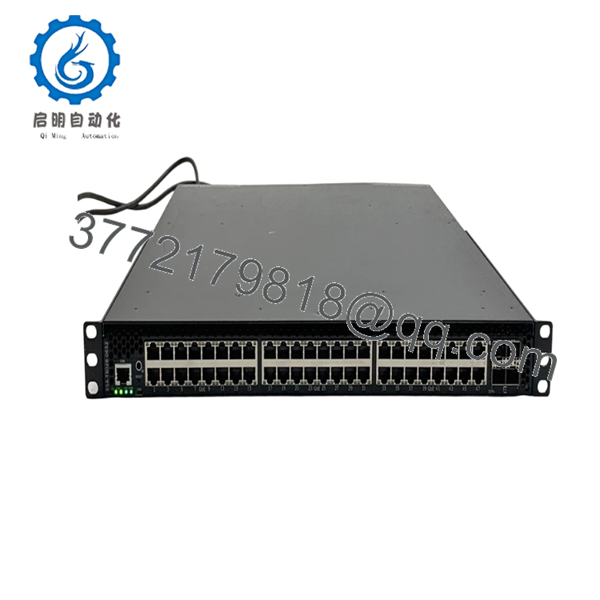
| Access Ports | 48 × 10/100/1000BASE-T RJ45 |
| Uplink Ports | 4 × 10GBASE-X SFP+ |
| Ethernet Mode | Full-duplex on all RJ45 ports |
| Management Interfaces | Console (COM), Micro-USB, CLI, SNMP |
| Switching Features | Layer 2/Layer 3 Enterprise Switching |
| Virtualization | Virtual Switch Bonding (VSB) Supported |
| Cooling | Front-to-Back Airflow |
| Power Supply | Modular AC Power Supply (ordered separately on some configurations) |
| Dimensions | 4.37 × 44.73 × 57.30 cm |
| Weight | Approximately 14.6 kg |
| Operating Media | Category 6 UTP, SFP+ Optical Modules |
| Compliance | IEC/UL 60950 and applicable regulatory certifications |
Always verify the installed ExtremeXOS/S-Series firmware version before replacing hardware in an existing network. Firmware consistency is particularly important when VSB or advanced routing features are enabled.
4. Product Introduction
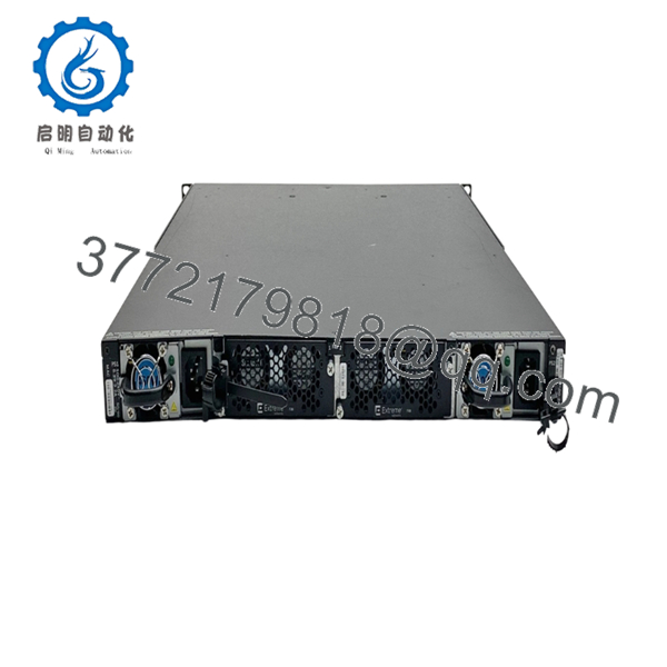
The Enterasys Networks SSA-T8028-0652 is an S-Series S180 standalone managed Ethernet switch designed for enterprise campus, aggregation, and data center edge deployments. It combines forty-eight Gigabit RJ45 access ports with four dedicated 10 Gigabit SFP+ uplinks in a 1U chassis, providing high-density connectivity for demanding network environments.
In production networks, this platform is commonly deployed where high port density, Virtual Switch Bonding, and advanced Layer 2/Layer 3 services are required while maintaining compatibility with existing Enterasys S-Series infrastructures. Since the platform is discontinued, New Surplus inventory remains a practical option for supporting installed systems.

- SSA-T8028-0652
- SSA-T8028-0652
5. Installation & Configuration Guide
Stage 1 – Pre-Installation Preparation (10 Minutes)
⚠️ Safety First
- Notify operations personnel of the maintenance window.
- Verify network redundancy before taking the switch offline.
- Perform Lock-Out/Tag-Out on the AC power source.
- Wait at least 5 minutes for internal capacitors to discharge.
Tools Required
- Grounded ESD wrist strap
- PH1 screwdriver
- Fluke 115 digital multimeter
- Cable identification labels
- Smartphone for documenting cable locations
Data Backup
- Export the running configuration.
- Save the startup configuration.
- Record management IP addresses.
- Document firmware version.
- Photograph all SFP+ modules and copper connections.
- Record Virtual Switch Bonding configuration if deployed.
Stage 2 – Removing the Existing Switch (10 Minutes)
- Label every network cable.
- Remove all SFP+ transceivers carefully.
- Disconnect RJ45 connections.
- Disconnect AC power.
- Remove rack mounting screws.
- Slide the chassis straight out while supporting its weight.
⚠️ Keep the original switch available until the replacement has successfully completed production testing.
Stage 3 – Installing the Replacement (10–15 Minutes)
- Wear a grounded ESD wrist strap.
- Verify the replacement model is exactly SSA-T8028-0652.
- Confirm the installed power supply matches the original configuration.
- Install the switch into the rack.
- Reinstall SFP+ modules.
- Restore network cabling.
- Reconnect power.
Self-Checklist
- ☑ Model number matches
- ☑ Power supply installed correctly
- ☑ SFP+ modules reinstalled
- ☑ Cabling restored
- ☑ Ground connection verified
Stage 4 – Power-On & Testing (15 Minutes)
Pre-Power Check
- Verify AC input voltage.
- Measure for shorts before energizing.
- Confirm all fan modules are installed securely.
Startup Procedure
- Apply AC power.
- Observe the POST sequence.
- Verify System LEDs indicate normal operation.
- Connect through the console or Micro-USB interface.
- Confirm firmware version.
- Restore the saved configuration if required.
- Verify VLAN operation.
- Test all four 10 Gb uplinks.
- Verify routing and VSB status where applicable.
⚠️ Troubleshooting Notes
- Solid fault LED: Check firmware compatibility first.
- No 10 Gb uplink: Verify that the installed SFP+ transceiver is supported by the platform.
- VSB member not joining: Confirm all participating switches are running compatible firmware revisions and matching VSB configurations.
Common Technical Pitfalls
❗ Firmware Revision Mismatch
I’ve seen engineers replace a failed SSA switch only to discover that the replacement shipped with a different software release. The hardware booted normally, but Virtual Switch Bonding never established correctly. Record the firmware version before removing the original switch and request a matching revision whenever possible.
❗ Power Supply Configuration
Some SSA models were supplied without AC power supplies as separate orderable components. Before commissioning, verify that the correct power supply is installed and fully seated.
❗ Unsupported Optical Modules
Third-party SFP+ optics may establish intermittent links or fail initialization. Always verify transceiver compatibility before assuming a hardware fault.
❗ Cabling Requirements
The RJ45 interfaces are designed for Category 6 UTP cabling. Poor cable quality or incorrect termination frequently causes intermittent Gigabit negotiation problems.
❗ Electrostatic Discharge (ESD)
Use a grounded wrist strap and ESD work surface throughout installation. Static damage often doesn’t produce immediate failures—it shows up later as intermittent port or transceiver issues.
Keep these checks in mind and you’ll avoid most of the troubleshooting typically encountered during SSA switch replacements.
6. Frequently Asked Questions (FAQ)
Q1. Can I hot-swap the SSA-T8028-0652?
No. This is a standalone switch rather than a chassis line card. Power the unit down before replacement to prevent hardware damage and configuration corruption.
Q2. Does this switch support 10 Gigabit uplinks?
Yes. The SSA-T8028-0652 includes four dedicated 10GBASE-X SFP+ uplink ports in addition to forty-eight Gigabit RJ45 access ports.
Q3. Is this model discontinued?
Yes. The SSA-T8028-0652 is a discontinued S-Series platform. Current availability primarily comes from New Surplus inventory and professionally tested refurbished equipment.
Q4. Will replacing the switch erase my configuration?
No, provided you’ve backed up the startup and running configurations. Export both before maintenance, then restore them after installing the replacement hardware.
Q5. Why is New Surplus hardware priced below the original OEM list?
The product is no longer manufactured. Pricing is determined by secondary-market availability rather than the original factory price. New Surplus equipment is unused legacy inventory, while refurbished equipment has been previously deployed and functionally tested.
Q6. How is each unit inspected before shipment?
Each SSA-T8028-0652 undergoes a documented quality inspection process that includes:
- OEM model and serial number verification
- Visual inspection for corrosion, damaged connectors, and repair marks
- Power-on self-test
- Console and Micro-USB communication verification
- RJ45 port testing
- SFP+ communication testing
- Fan and cooling verification
- Firmware version documentation
- Electrical inspection, including insulation and grounding checks where applicable
- Final QC approval
- ESD-safe packaging with anti-static protection and heavy-duty shipping materials
Power-on videos, functional test reports, and inspection photographs are available upon request.



