
 WhatsApp: +86 16626708626
 Email:
  Phone: +86 16626708626
Description
Key Technical Specifications
- Linear Measurement Range: 2 mm (80 mils)
- Initial Air Gap: 0.5 mm (20 mils)
- Incremental Scale Factor (ISF): 8 V/mm (203.2 mV/mil) ± 5% at 0 to 45°C
- Deviation from Best Fit Straight Line (DSL): ± 0.025 mm (± 1 mil) at 0 to 45°C
- Minimum Target Shaft Diameter: 25 mm (0.79 in)
- Target Material: 42CrMo4 (AISI/SAE 4140) ferromagnetic steel, standard
- Protection Class: IP66 per IEC 60529
- Operating Temperature: Sensor + 1 m cable, −35 to +180°C (−31 to +356°F); cable/connector beyond that, −35 to +150°C (−31 to +302°F)
- Materials: PEEK tip, stainless steel case, PTFE cable, nickel-plated brass connector
- Weight: Approx. 100 g (3.53 oz) with 1 m cable
- Hazardous Area Rating: Intrinsic safety (ia) and non-sparking (nA), temperature classified T6 (Ta ≤ 64°C), T4 (Ta ≤ 114°C), T3 (Ta ≤ 160°C) — actual area classification depends on the paired converter, not the sensor alone
Product Introduction
The Epro 9200-00021N (PR6423/002-011) is an 8 mm eddy current sensor built for continuous, non-contact monitoring of radial and axial shaft displacement on turbines, compressors, gearboxes, pumps, and fans. It runs as part of MMS 3000 and MMS 6000 machinery protection systems, paired with a CON021 or CON041 converter/barrier depending on your hazardous area requirements.
The 2 mm linear range and 8 V/mm scale factor make it a drop-in match against systems already running standard PR6423 probes, and the −35 to +180°C sensor rating covers hot-side turbine casing mounts that push weaker sensors past their limits.
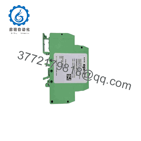
9200-00021N
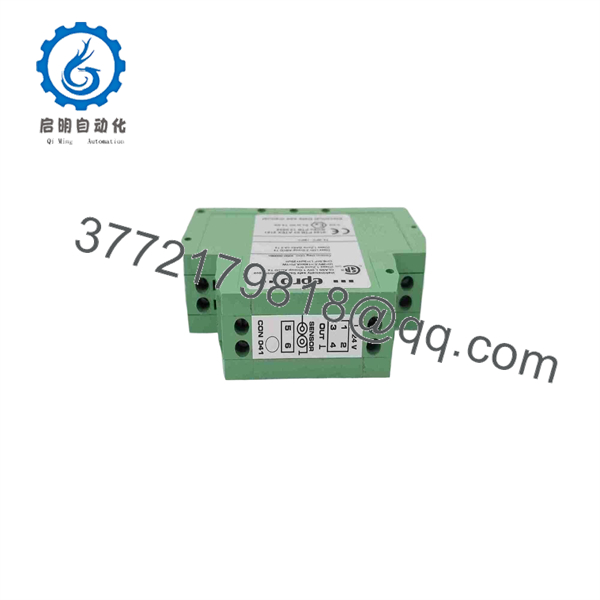
9200-00021N
Troubleshooting Quick Reference
| Symptom | Possible Cause | Relevance to this Part | Quick Check Method | Recommendation |
|---|---|---|---|---|
| No output voltage at converter | Sensor or cable open/short | ✅ High | Measure DC resistance at the connector; compare to known-good probe | Replace sensor if resistance is out of spec |
| Output voltage but reading unstable/noisy | Target surface finish or gap misalignment | ❌ Low | Recheck 0.5 mm initial air gap and target material | Reset gap before condemning the sensor |
| Reading pegged at rail (full negative or positive) | Sensor failure or gap set outside 2 mm linear range | ✅ High | Verify gap voltage against the −2 to −18 V or −4 to −20 V operating range | Sensor replacement likely if gap is confirmed correct |
| Slow drift in baseline reading over time | Sensor tip wear, target corrosion, or thermal drift | ⚠️ Medium | Compare current reading against original commissioning baseline | Confirm converter zero/span before replacing sensor |
| Total signal loss under vibration | Cable connector or armor damage | ❌ Low | Inspect Lemo connector and cable routing for mechanical damage | Cable repair often resolves this before sensor swap |
Send the gap-voltage trend and converter model to technical support if the fault doesn’t isolate cleanly — sensor vs. converter vs. wiring gets misdiagnosed constantly on these systems.
Frequently Asked Questions (FAQ)
Is this sensor hazardous-area rated on its own?
The sensor itself is rated for intrinsic safety (ia) and non-sparking (nA) service, with T6/T4/T3 temperature classifications depending on ambient. But the actual area classification for your installation depends on which converter it’s paired with — check the converter’s documentation, not just the sensor’s.
Can I substitute this for a different PR6423 variant?
Only if the case thread (M10x1 vs. 3/8″-24 UNF), cable length, and armor option all match your existing installation. The PR6423 family covers a wide ordering matrix — swapping in a different suffix can mean a different cable length or connector style than what’s already run through your conduit.
Why is this priced below a factory-new quote from Emerson?
Because it’s typically New Surplus or Refurbished stock circulating through the secondary market, not a direct factory order. Confirm condition and get a test report before buying — for a safety/protection-loop sensor, that’s not optional.
Does swapping this sensor require re-commissioning the whole loop?
Yes, expect to redo gap-voltage verification. The datasheet specifies an 8 V/mm scale factor and a nominal air gap target — you’ll need to reset and verify the gap on install, not just plug and go.
What’s the actual measurement range I’m getting?
2 mm linear range with a 0.5 mm initial air gap — that’s the OEM spec, not a rounded marketing number. Don’t confuse this with the full mechanical travel of the probe tip; it’s the calibrated linear window.
Is this sensor repairable, or is it throwaway once it fails?
These are sealed units — PEEK tip, stainless housing, PTFE cable — not designed for field repair. A failed unit gets replaced, not serviced.



